Non-Contact Proximity Probes
Machine Saver probes are at the forefront of eddy current proximity probe design, are well acknowledged in the industry, and are compatible with all significant transducer producers. The American Petroleum Institute Standard 670 is completely complied with by the MS-Series probes (API-670). We guarantee the viability and durability of these proximity probes and associated systems for up to ten years, with a default warranty of three years that is extendable to five years at the customer's request. We are the only known American manufacturer of mass-produced vibration probes. In order to support a preventative maintenance program and machinery diagnostics, today's high-performance eddy current proximity sensors provide continuous condition monitoring information and trip monitored machines when necessary. Our leading proximity solutions provide full interoperability and exceptional performance in challenging environments.
- Non-Contact Proximity Probe System
- 3309 (Focus View) Series
- 3300 Series
- 3300 5mm Specifications and Dimensions
- 3300 5mm Ordering
- 3300 8mm Specifications and Dimensions
- 3300 8mm Ordering
- 3300 11mm Specifications and Dimensions
- 3300 11mm Ordering
- 3000 Series
- 7200 Series
Non-Contact Proximity Probe System
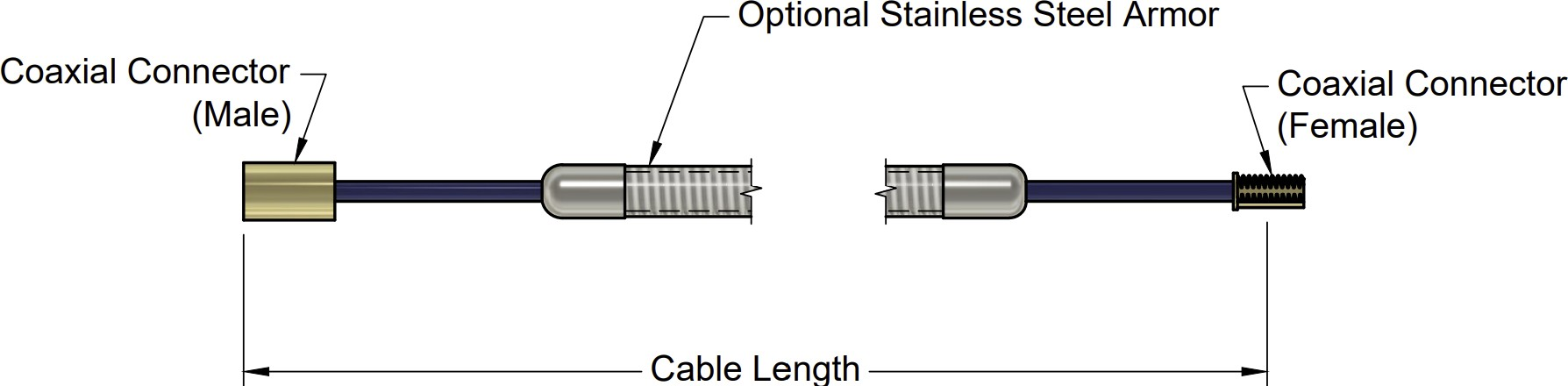
An industrial non-contact proximity probe typically consists of a coil, a mandrel, and a cable. Here's how these components are combined to make the probe:
-
Coil: The coil is typically made of a fine wire wound around a former, which is usually made of a non-conductive material. The coil is a critical component of the probe, as it generates the electromagnetic field that interacts with the target object.
-
Mandrel: The mandrel is a tubular structure that is typically made of a non-magnetic material, such as stainless steel or titanium. The coil is wound around the mandrel, which helps to keep it in place and maintain its shape.
-
Cable: The cable is used to connect the probe to the driver and signal conditioning electronics, which are typically located outside the sensing environment. The cable is typically made of a shielded coaxial cable that is designed to minimize noise and interference.
To assemble the probe, the coil is wound around the mandrel, which is then typically coated with a layer of insulating material to protect the coil from the environment. The cable is then attached to the coil, and the entire assembly is typically mounted on a support structure, such as a bracket or flange.
When the probe is in operation, the electromagnetic field generated by the coil interacts with the target object, which induces eddy currents in the object. These eddy currents generate a secondary electromagnetic field that is detected by the coil, and the resulting signal is then transmitted through the cable to the driver and signal conditioning electronics for processing and analysis.
An industrial non-contact proximity probe typically consists of the following components:
-
Sensor Head: This is the part of the probe that detects changes in position and proximity of the target. It typically uses electromagnetic or capacitive sensing technology.
-
Signal Processing Unit: This unit is responsible for processing the sensor signals and converting them into electrical signals that can be read by a monitoring system or control unit.
-
Amplifier: The amplifier boosts the signal from the sensor head to improve its accuracy and reliability.
-
Cable: This connects the sensor head to the signal processing unit and can be shielded to reduce electromagnetic interference.
-
Mounting Hardware: This allows the probe to be securely attached to the machine or equipment being monitored.
-
Power Supply: The probe requires a power source, which can be supplied by batteries or an external power supply.
-
Output Display: This component displays the output of the probe, which can include the distance or position of the target.
3309 (Focus View) Series
3309 (Focus View) Specifications and Dimensions
Specifications
|
Parameter |
Value |
|
Linear Range |
2.0 mm (80 mils). Linear range begins at 0.38 mm (15 mils) from target and is from 0.38 to 2.41mm (15 to 95 mils). |
Incremental Scale Factor (ISF)
|
7.87 V/mm (200 mV/mil) +12.5%/–20% including interchangeability error when measured in increments of 0.25 mm (10 mils) over the 1.5 mm (60 mils) linear range |
|
Deviation from best fit straight line (DSL) |
Less than ±0.06 mm (± 2.3 mils) |
|
Frequency response |
0 to 10kHz (-3 dB) typical, with up to 100 meters (300 feet) of field wiring. |
|
Target Size |
Minimum: 8.9 mm (0.35 in) diameter Recommended minimum: 13mm (0.5 in) diameter Axial position measurements on shaft diameters smaller than 13mm (0.5 in) will generally result in a change in scale factor. Reducing the gap between the probe and target will help limit the change in scale factor. |
Shaft Diameter |
Minimum (standard X-Y probe configuration): 30 mm (1.2 in) Minimum (X-Y proximity probes offset axially by 23 mm (0.9 in)): 20 mm (0.8 in) Measurements on shaft diameters smaller than 30 mm (1.2 in) usually require close spacing of radial vibration or axial position transducers. This creates the potential for their electromagnetic emitted fields to interact with one another (cross-talk), resulting in erroneous readings. To prevent cross-talk, maintain minimum separation of m transducer tips of at least 25 mm (1.0 in) for axial position measurements or 23 mm (0.9 in) for radial vibration measurements |
|
Probe Tip Material |
Polyphenylene sulfide (PPS). |
|
Probe Cable Specifications |
75 Ω coaxial, fluoroethylene propylene (FEP) insulated probe cable in the following total probe lengths: 0.5, 1, 5, or 7 meters. |
|
Extension Cable Material |
75 Ω coaxial, fluoroethylene propylene (FEP) insulated. |
|
System Length |
5 or 7 meters including extension cable |
|
Extension Cable Armor (optional) |
Flexible AISI 302 SST with/without FEP outer jacket |
|
Tensile Strength (maximum rated) |
220 N (50 lb) probe case to probe lead. 220 N (50 lb) at probe lead to extension cable connectors. 220 N (50 lb) probe case to stainless steel armor |
|
Connector material |
Gold-plated brass |
|
Recommended Connector Torque |
Hand tightened |
|
Maximum torque |
0.56 N• m (5 in• lb) |
|
Minimum bend Radius (with or without SS armor) |
25.4 mm (1.0 in) |
|
Probe Temperature Range Operating Temperature |
-34°C to +177°C (-30°F to +351°F) |
|
Storage Temperature |
-51°C to +177°C (-60°F to +351°F) |
|
Extension Cable Operating and Storage Temperature |
-51°C to +177°C (-60°F to +351°F) |
|
Relative Humidity |
100% condensing, non-submersible when connectors are protected |
Imperial/US
Metric


Reverse Mount - Metric or Imperial

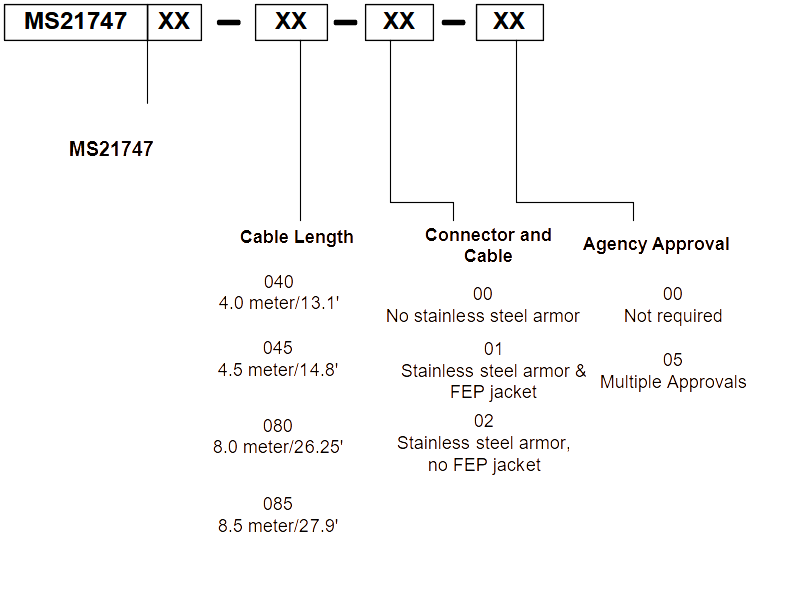
Extension Cables

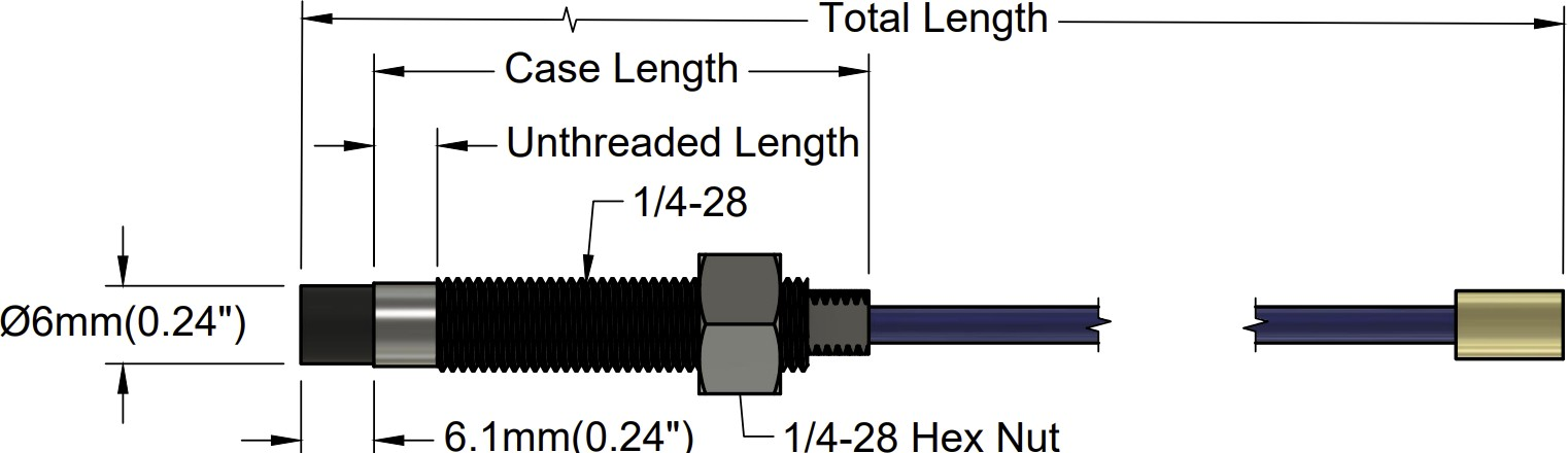
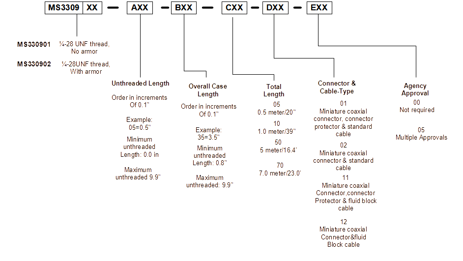
3309 (Focus View) Ordering
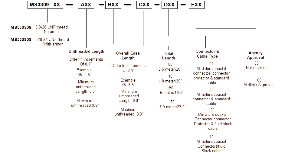
Imperial/US
| Model | A: Unthreaded Length | B: Overall Case Length | C: Total Length | D: Connector & Cable Type | E: Agency Approval |
|
MS330901 ¼-28 UNF thread, no armor |
Order in increments of 0.1 in |
Order in increments of 0.1 in |
05 = 0.5 Meter/20 in |
01 = Miniature coaxial connector, connector protector & standard cable |
00 = Not Required |
|
MS330902 ¼-28 UNF thread, with armor |
Example: 05 = 0.5 in | Example: 35 = 3.5 in |
10 = 1.0 meter/39 in |
02 = Miniature coaxial connector & standard cable |
05 = Multiple Approvals |
|
MS330908 ⅜-28 UNF thread, no armor |
Minimum unthreaded length: 0 mm | Minimum unthreaded length: 20 mm |
50 = 5.0 meter/16.4 feet |
11 = Miniature coaxial connector, connector protector & fluid block cable | |
|
MS330909 ⅜-24 UNF thread, with armor |
Maximum unthreaded length: 230 mm | Maximum unthreaded length: 250 mm |
70 = 7.0 meter/23.0 feet |
12 Miniature coaxial connector & fluid block cable |
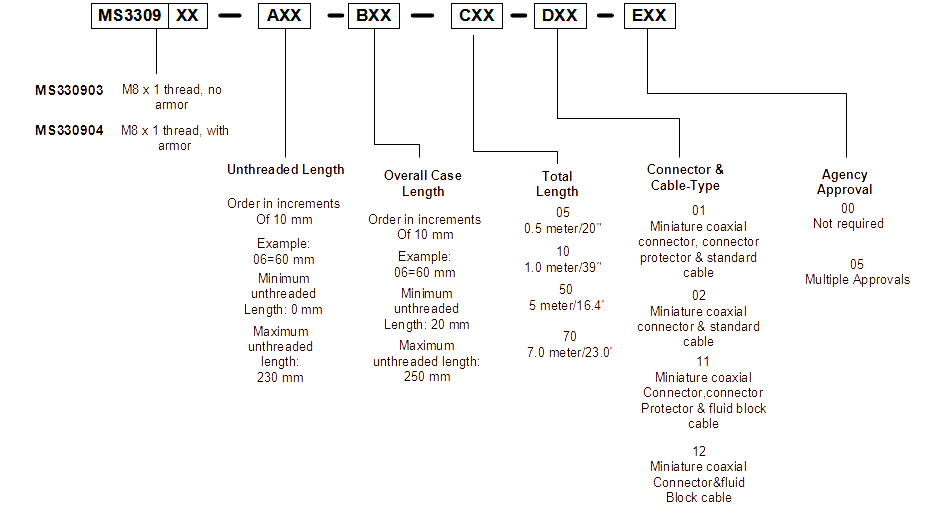
Metric
| Model | A: Unthreaded Length | B: Overall Case Length | C: Total Length | D: Connector & Cable Type | E: Agency Approval |
|
MS330903 M8 x 1 thread, no armor |
Order in increments of 10 mm | Order in increments of 10 mm |
05 = 0.5 Meter/20 in |
01 = Miniature coaxial connector, connector protector & standard cable |
00 = Not Required |
|
MS330904 M8 x 1 thread, with armor |
Example: 06 = 60 mm | Example: 06 = 60 mm |
10 = 1.0 meter/39 in |
02 = Miniature coaxial connector & standard cable |
05 = Multiple Approvals |
|
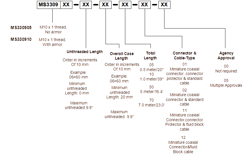
MS330905 M10 x 1 thread, no armor |
Minimum unthreaded length: 0 mm | Minimum unthreaded length: 20 mm |
50 = 5.0 meter/16.4 feet |
||
|
MS330910 M10 x 1 thread, with armor |
Maximum unthreaded length: 230 mm | Maximum unthreaded length: 250 mm |
90 = 9.0 meter/29.5 feet |
|
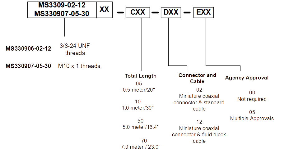
Reverse Mount
Option Descriptions
MS330906-02-12-CXX-DXX-EXX
MS330907-05-30-CXX-DXX-EXX
| Model | AA: Total Length | BB: Connector & Cable Type | CC: Agency Approval |
|
MS330906-02-12 ⅜-24 UNF threads |
05 = 0.5 meter/20 in | 01 = Miniature coaxial connector, connector protector & standard cable | 00 = Not Required |
|
MS330907-05-30 M10 x 1 threads |
10 = 1.0 meter/39 in | 02 = Miniature coaxial connector & standard cable | 05 = Multiple Approvals |
| 50 = 5.0 meter/16.4 feet | |||
| 90 = 9.0 meter/29.5 feet |
Extension Cable
Extension Cable Option Descriptions
MS330930-AXXX-BXX-CXX
| Model | AA: Cable Length | BB: Connector & Cable Type | CC: Agency Approval |
| MS330930 |
040=4.0 meter/13.1 feet |
00 = No stainless steel armor. | 00 = Not Required |
|
045=4.5 meter/14.8 feet |
01 = Stainless steel armor & FEP Jacket. | 05 = Multiple Approvals | |
|
060=6.0 meter/19.7 feet |
02 = Stainless steel armor, no FEP Jacket | ||
|
065=6.5 meter/21.3 feet |
|||
|
080=8.0 meter/26.2 feet |
|||
|
085=8.5 meter/27.8 |
3300 Series
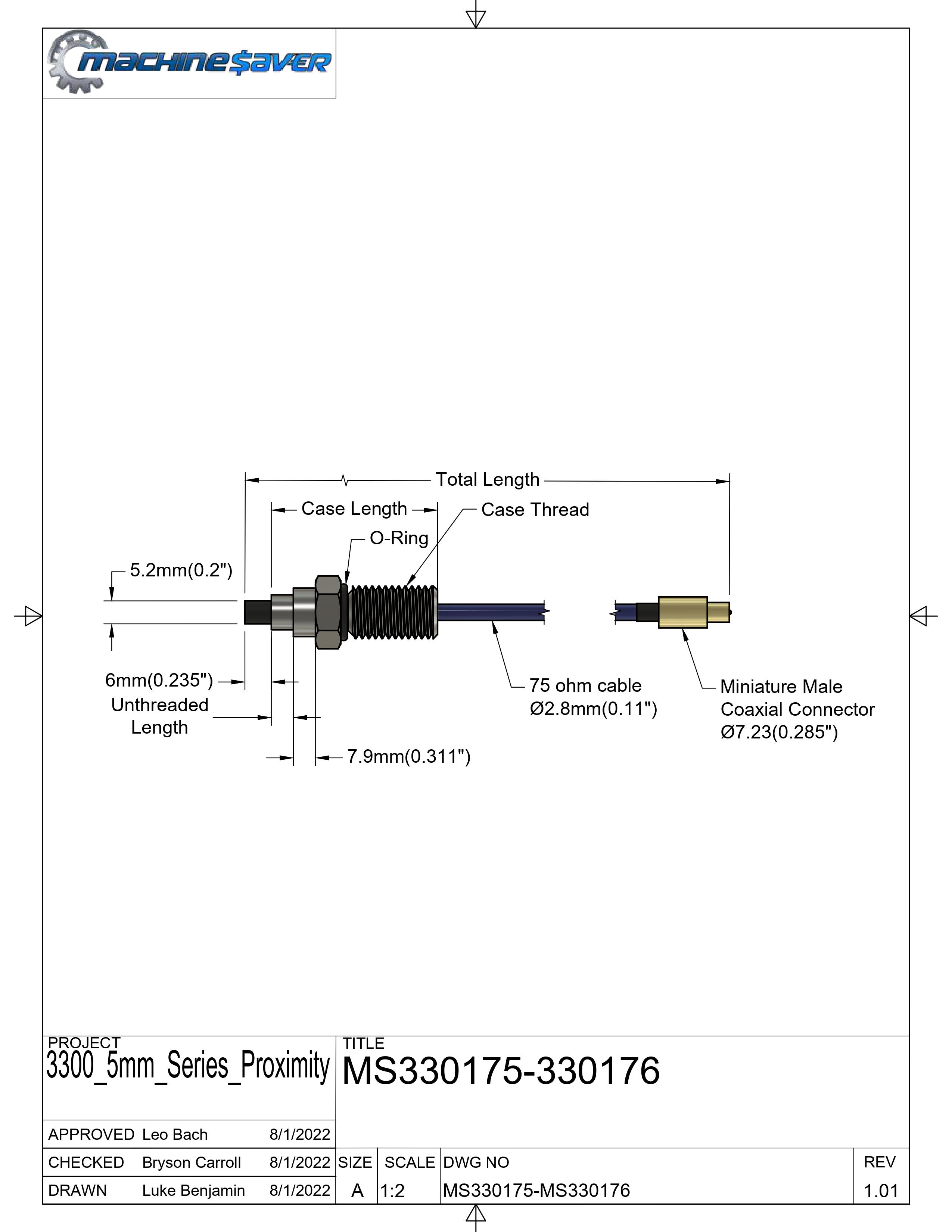
3300 5mm Specifications and Dimensions
|
Parameter |
Value |
|
Linear Range |
2.0 mm (80 mils). Linear range begins at 0.38 mm (15 mils) from target and is from 0.38 to 2.41mm (15 to 95 mils). |
Incremental Scale Factor (ISF)
|
7.87 V/mm (200 mV/mil) +/-6.5% error (including interchangeability error) when measured in 10 mil increments when measured in increments of 0.25 mm (10 mils) over the 2.0 mm (80 mils) linear range |
|
Deviation from best fit straight line (DSL) |
1 to 5 meter system length is less than ±0.025 mm (±1 mil). 9 meter system length is less than ±0.038 mm (±1.5 mil). |
|
Frequency response |
0 to 10kHz (-3 dB) typical, with up to 100 meters (300 feet) of field wiring.
|
|
Target Size |
Minimum flat: 25 mm (1.0 in) diameter Minimum perpendicular to shaft 50mm (2 in.) Recommended perpendicular to shaft 75mm (3 in.) |
|
Probe Tip Material |
Polyphenylene sulfide (PPS). |
|
Probe Case Material |
AISI 303 or 304 stainless steel (SST). |
|
Probe Cable Specifications |
75 Ω coaxial, fluoroethylene propylene (FEP) insulated probe cable in the following total probe lengths: 0.5, 1, 5, or 9 meters |
|
Extension Cable Material |
75 Ω coaxial, fluoroethylene propylene (FEP) insulated |
|
System Length |
1 (probe only), 5 or 9 meters including extension cable |
|
Extension Cable Armor (optional) |
Flexible AISI 302 SST with/without FEP outer jacket |
|
Tensile Strength (maximum rated) |
220 N (50 lb) probe case to probe lead. 220 N (50 lb) at probe lead to extension cable connectors. 220 N (50 lb) probe case to stainless steel armor |
|
Connector material |
Gold-plated brass |
|
Recommended Connector Torque |
Hand tightened |
|
Maximum torque |
0.56 N• m (5 in• lb) |
|
Minimum bend Radius (with or without SS armor) |
25.4 mm (1.0 in) |
|
Probe Temperature Range Operating Temperature |
-34°C to +177°C (-30°F to +350°F) |
|
Storage Temperature |
-51°C to +177°C (-60°F to +350°F) |
|
Extension Cable Operating and Storage Temperature |
-51°C to +177°C (-60°F to +350°F) |
|
Relative Humidity |
100% condensing, non-submersible when connectors are protected |
Imperial/US
Metric
Reverse Mount - Metric or Imperial

Extension Cables

Electrical
Linear Range:
2.0 mm (80 mils). Linear range begins at 0.38 mm (15 mils) from target and is from 0.38 to 2.41mm (15 to 95 mils).
Incremental Scale Factor (ISF):
7.87 V/mm (200 mV/mil) +/-6.5% error (including interchangeability error) when measured in 10
mil increments when measured in increments of 0.25 mm (10 mils) over the 2.0 mm (80 mils)
linear range.
Deviation from best fit straight line (DSL):
1 to 5 meter system length is less than ±0.025 mm (±1 mil).
9 meter system length is less than ±0.038 mm (±1.5 mil).
Frequency response:
0 to 10kHz (-3 dB) typical, with up to 100 meters (300 feet) of field wiring.
Target Size:
Minimum flat: 25 mm (1.0 in) diameter.
Minimum perpendicular to shaft 50mm (2 in.).
Recommended perpendicular to shaft 75mm (3 in.).
Mechanical
Probe Tip Material:
Polyphenylene sulfide (PPS).
Probe Case Material:
AISI 303 or 304 stainless steel (SST).
Probe Cable Specifications:
75 Ω coaxial, fluoroethylene propylene (FEP) insulated probe cable in the following total probe lengths: 0.5, 1, 5, or 9 meters.
Extension Cable Material:
75 Ω coaxial, fluoroethylene propylene (FEP) insulated.
System Length:
1 (probe only), 5 or 9 meters including extension cable
Extension Cable Armor (optional):
Flexible AISI 302 SST with/without FEP outer jacket.
Tensile Strength (maximum rated):
220 N (50 lb) probe case to probe lead. 220 N (50 lb) at probe lead to extension cable connectors. 220 N (50 lb) probe case to stainless steel armor.
Connector material:
Gold-plated brass
Recommended Connector Torque:
Hand tightened
Maximum torque:
0.56 N• m (5 in• lb)
Minimum bend Radius (with or without SS armor):
25.4 mm (1.0 in)
Environmental Limits
Probe Temperature Range
Operating Temperature:
-34°C to +177°C (-30°F to +350°F)
Storage Temperature:
-51°C to +177°C (-60°F to +350°F)
Extension Cable Temperature Range
Operating and Storage Temperature:
-51°C to +177°C (-60°F to +350°F)
Storage Temperature:
-51°C to +177°C (-60°F to +350°F)
Proximity Sensor Temperature Range
Operating Temperature:
-35°C to +177°C (-31°F to +350°F)
Storage Temperature:
-51°C to +177°C (-60°F to +350°F)
Relative Humidity:
100% condensing, non-submersible when connectors are protected
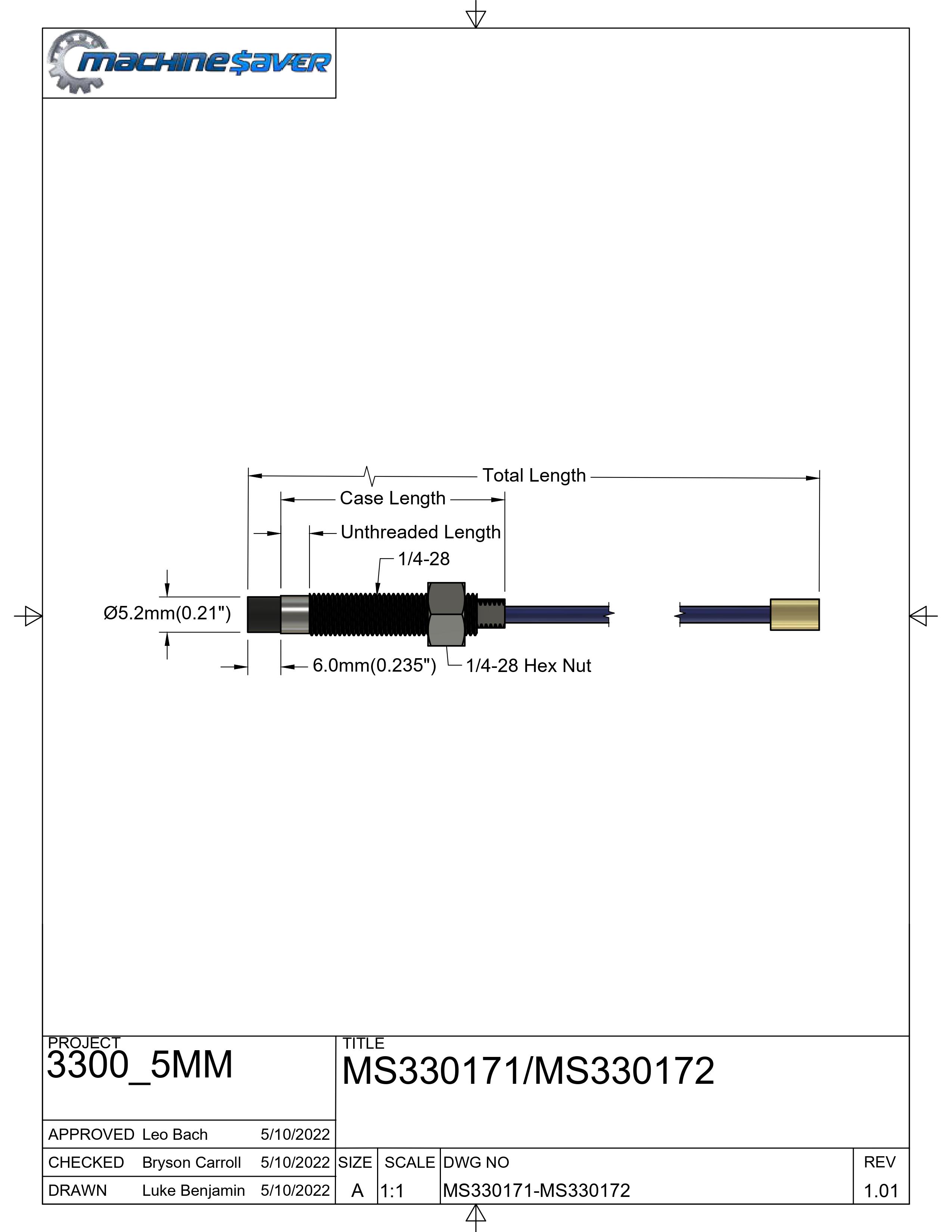
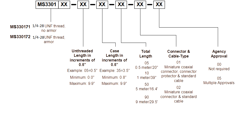
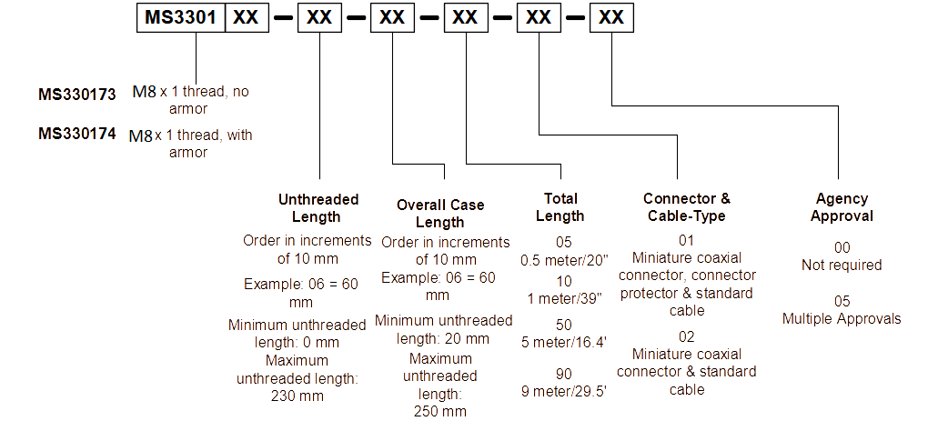
3300 5mm Ordering
Imperial/US
| Model | AA: Unthreaded Length | BB: Overall Case Length | CC: Total Length | DD: Connector & Cable Type | EE: Agency Approval |
| MS330171-AA-BB-CC-DD-EE 1/4-28 UNF thread, no armor |
Order in increments of 0.5 in | Order in increments of 0.5 in |
05 = 0.5 meter/20 in |
01 = Miniature coaxial connector, connector protector & standard cable |
00 = Not Required |
| MS330172-AA-BB-CC-DD-EE 1/4-28 UNF thread, with armor |
Example: 05 = 0.5 in | Example: 35 = 3.5 in |
10 = 1.0 meter/39 in |
02 = Miniature coaxial connector & standard cable |
05 = Multiple Approvals |
| Minimum unthreaded length: 0.0 in | Minimum unthreaded length: 0.8 in |
50 = 5.0 meter/16.4 feet |
|||
| Maximum unthreaded length: 9.9 in | Maximum unthreaded length: 9.9 in |
90 = 9.0 meter/29.5 feet |
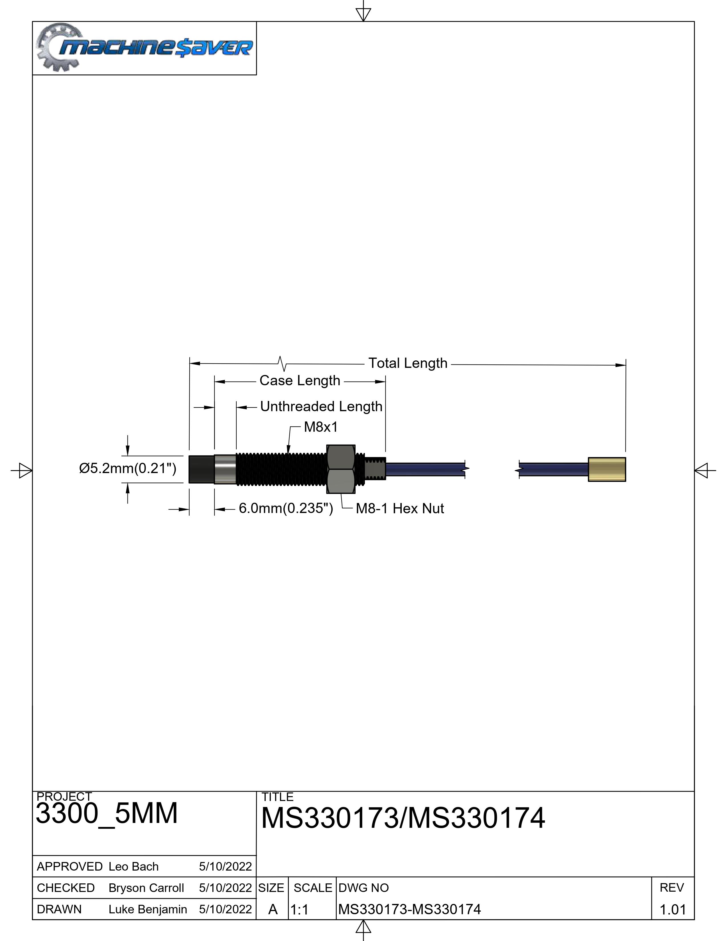
Metric
| Model | AA: Unthreaded Length | BB: Overall Case Length | CC: Total Length | DD: Connector & Cable Type | EE: Agency Approval |
| MS330173-AA-BB-CC-DD-EE M8 x 1 thread, no armor |
Order in increments of 10 mm | Order in increments of 10 mm |
05 = 0.5 Meter/20 in |
01 = Miniature coaxial connector, connector protector & standard cable |
00 = Not Required |
| MS330174-AA-BB-CC-DD-EE M8 x 1 thread, with armor |
Example: 06 = 60 mm | Example: 06 = 60 mm |
10 = 1.0 meter/39 in |
02 = Miniature coaxial connector & standard cable |
05 = Multiple Approvals |
| Minimum unthreaded length: 0 mm | Minimum unthreaded length: 20 mm |
50 = 5.0 meter/16.4 feet |
|||
| Maximum unthreaded length: 230 mm | Maximum unthreaded length: 250 mm |
90 = 9.0 meter/29.5 feet |
|
Reverse Mount
| Model | AA: Total Length | BB: Connector & Cable Type | CC: Agency Approval |
| MS330175-02-12-AA-BB-CC ⅜-24 UNF threads |
05 0.5 meter/20 in |
01 = Miniature coaxial connector, connector protector & standard cable | 00 = Not Required |
| MS330176-05-30-AA-BB-CC M10 X 1 threads |
10 1.0 meter/39 in |
02 = Miniature coaxial connector & standard cable | 05 = Multiple Approvals |
| 50 5.0 meter/16.4 feet |
|||
| 90 9.0 meter/29.5 feet |
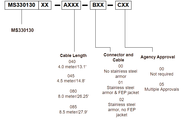
Extension Cable
| Model | AA: Cable Length | BB: Connector & Cable Type | CC: Agency Approval |
| MS330130 | 05 0.5 meter/20 in |
00 = No stainless steel armor. | 00 = Not Required |
| 10 1.0 meter/39 in |
01 = Stainless steel armor & FEP Jacket. | 05 = Multiple Approvals | |
| 50 5.0 meter/16.4 feet |
02 = Stainless steel armor, no FEP Jacket | ||
| 90 9.0 meter/29.5 feet |
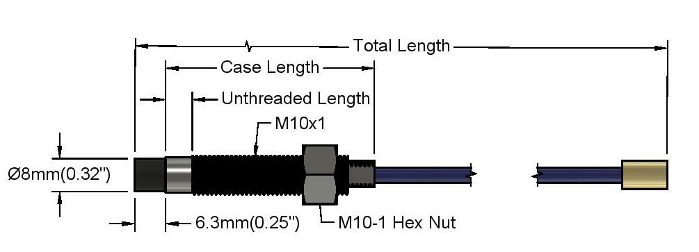
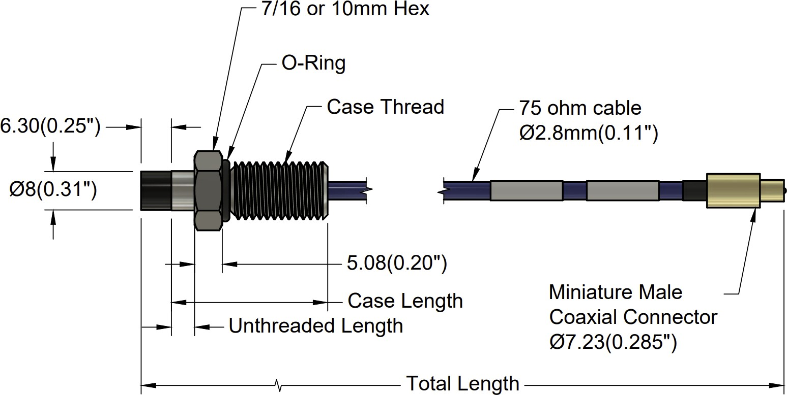
3300 8mm Specifications and Dimensions
|
Parameter |
Value |
|
Linear Range |
2.0 mm (80 mils). Linear range begins at 0.38 mm (15 mils) from target and is from 0.38 to 2.41 mm (15 to 95 mils). |
Incremental Scale Factor (ISF)
|
7.87 V/mm (200 mV/mil) +/-6.5% error (including interchangeability error) when measured in 10 mil increments when measured in increments of 0.25 mm (10 mils) over the 2.0 mm (80 mils) linear range |
|
Deviation from best fit straight line (DSL) |
1 to 5 meter system length is less than ±0.025 mm (±1 mil). 9 meter system length is less than ±0.038 mm (±1.5 mil). |
|
Frequency response |
0 to 10kHz (-3 dB) typical, with up to 100 meters (300 feet) of field wiring.
|
|
Target Size |
Minimum flat: 25 mm (1.0 in) diameter Minimum perpendicular to shaft 50mm (2 in.) Recommended perpendicular to shaft 75mm (3 in.) |
|
Probe Tip Material |
Polyphenylene sulfide (PPS). |
|
Probe Case Material |
AISI 303 or 304 stainless steel (SST). |
|
Probe Cable Specifications |
75 Ω coaxial, fluoroethylene propylene (FEP) insulated probe cable in the following total probe lengths: 0.5, 1, 5, or 9 meters |
|
Extension Cable Material |
75 Ω coaxial, fluoroethylene propylene (FEP) insulated |
|
System Length |
1 (probe only), 5 or 9 meters including extension cable |
|
Extension Cable Armor (optional) |
Flexible AISI 302 SST with/without FEP outer jacket |
|
Tensile Strength (maximum rated) |
220 N (50 lb) probe case to probe lead. 220 N (50 lb) at probe lead to extension cable connectors. 220 N (50 lb) probe case to stainless steel armor |
|
Connector material |
Gold-plated brass |
|
Recommended Connector Torque |
Hand tightened |
|
Maximum torque |
0.56 N• m (5 in• lb) |
|
Minimum bend Radius (with or without SS armor) |
25.4 mm (1.0 in) |
|
Probe Temperature Range Operating Temperature |
-34°C to +177°C (-30°F to +350°F) |
|
Storage Temperature |
-51°C to +177°C (-60°F to +350°F) |
|
Extension Cable Operating and Storage Temperature |
-51°C to +177°C (-60°F to +350°F) |
|
Relative Humidity |
100% condensing, non-submersible when connectors are protected |
Imperial/US

Metric

Reverse Mount - Metric or Imperial
Extension Cables
Electrical
Linear Range:
2.0 mm (80 mils). Linear range begins at 0.38 mm (15 mils) from target and is from 0.38 to 2.41
mm (15 to 95 mils).
Incremental Scale Factor (ISF):
7.87 V/mm (200 mV/mil) +/-6.5% error (including interchangeability error) when measured in 10
mil increments when measured in increments of 0.25 mm (10 mils) over the 2.0 mm (80 mils)
linear range.
Deviation from best fit straight line (DSL):
1 to 5 meter system length is less than ±0.025 mm (±1 mil).
9 meter system length is less than ±0.038 mm (±1.5 mil).
Frequency response:
0 to 10kHz (-3 dB) typical, with up to 100 meters (300 feet) of field wiring.
Target Size:
Minimum flat: 25 mm (1.0 in) diameter.
Minimum perpendicular to shaft 50mm (2 in.).
Recommended perpendicular to shaft 75mm (3 in.).
Mechanical
Probe Tip Material:
Polyphenylene sulfide (PPS).
Probe Case Material:
AISI 303 or 304 stainless steel (SST).
Probe Cable Specifications:
75 Ω coaxial, fluoroethylene propylene (FEP) insulated probe cable in the following total probe lengths: 0.5, 1, 5, or 9 meters.
Extension Cable Material:
75 Ω coaxial, fluoroethylene propylene (FEP) insulated.
System Length:
1 (probe only), 5 or 9 meters including extension cable
Extension Cable Armor (optional):
Flexible AISI 302 SST with/without FEP outer jacket.
Tensile Strength (maximum rated):
220 N (50 lb) probe case to probe lead. 220 N (50 lb) at probe lead to extension cable connectors. 220 N (50 lb) probe case to stainless steel armor.
Connector material:
Gold-plated brass
Recommended Connector Torque:
Hand tightened
Maximum torque:
0.56 N• m (5 in• lb)
Minimum bend Radius (with or without SS armor):
25.4 mm (1.0 in)
Environmental Limits
Probe Temperature Range
Operating Temperature:
-34°C to +177°C (-30°F to +350°F)
Storage Temperature:
-51°C to +177°C (-60°F to +350°F)
Extension Cable Temperature Range
Operating and Storage Temperature:
-51°C to +177°C (-60°F to +350°F)
Storage Temperature:
-51°C to +177°C (-60°F to +350°F)
Proximity Sensor Temperature Range
Operating Temperature:
-35°C to +177°C (-31°F to +350°F)
Storage Temperature:
-51°C to +177°C (-60°F to +350°F)
Relative Humidity:
100% condensing, non-submersible when connectors are protected
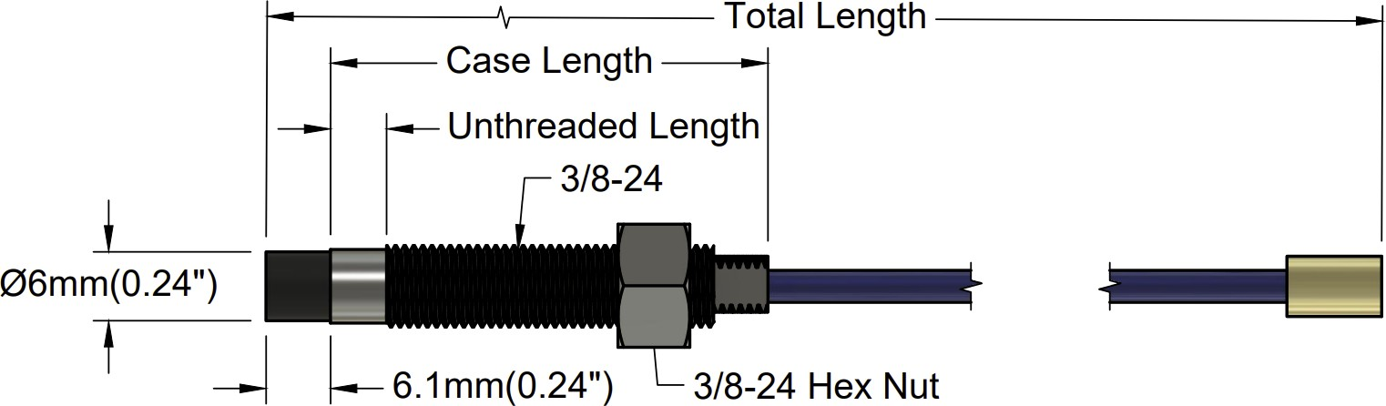
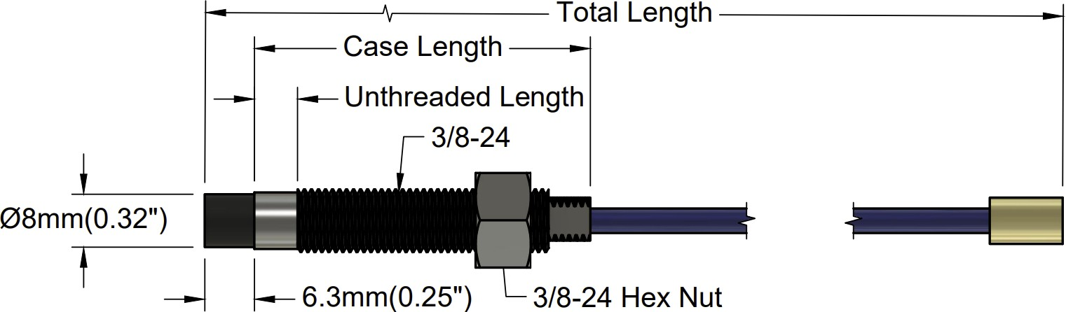
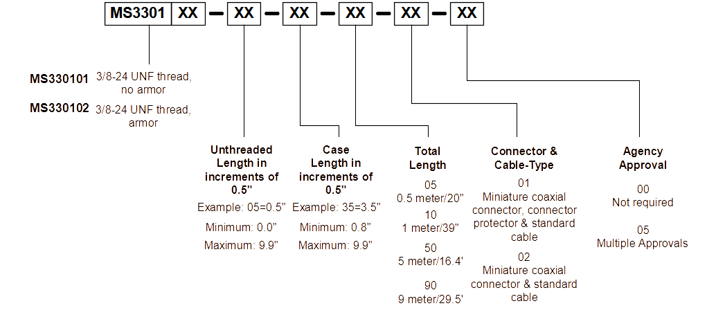
3300 8mm Ordering
Imperial/US
| Model | AA: Unthreaded Length | BB: Overall Case Length | CC: Total Length | DD: Connector & Cable Type | EE: Agency Approval |
| MS330101-AA-BB-CC-DD-EE 3/8-24 UNF thread, no armor |
Order in increments of 0.5 in | Order in increments of 0.5 in |
05 = 0.5 meter/20 in |
01 = Miniature coaxial connector, connector protector & standard cable |
00 = Not Required |
| MS330102-AA-BB-CC-DD-EE 3/8-24 UNF thread, with armor |
Example: 05 = 0.5 in | Example: 35 = 3.5 in |
10 = 1.0 meter/39 in |
02 = Miniature coaxial connector & standard cable |
05 = Multiple Approvals |
| Minimum unthreaded length: 0.0 in | Minimum unthreaded length: 0.8 in |
50 = 5.0 meter/16.4 feet |
|||
| Maximum unthreaded length: 9.9 in | Maximum unthreaded length: 9.9 in |
90 = 9.0 meter/29.5 feet |
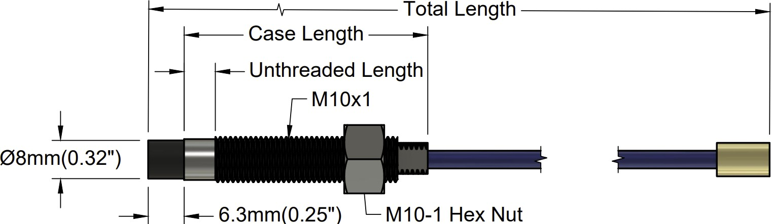
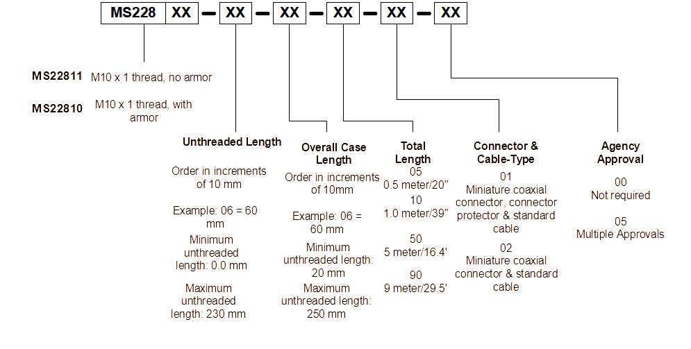
Metric
| Model | AA: Unthreaded Length | BB: Overall Case Length | CC: Total Length | DD: Connector & Cable Type | EE: Agency Approval |
| MS330103-AA-BB-CC-DD-EE M10 x 1 thread, no armor |
Order in increments of 10 mm | Order in increments of 10 mm |
05 = 0.5 Meter/20 in |
01 = Miniature coaxial connector, connector protector & standard cable |
00 = Not Required |
| MS330104-AA-BB-CC-DD-EE M10 x 1 thread, with armor |
Example: 06 = 60 mm | Example: 06 = 60 mm |
10 = 1.0 meter/39 in |
02 = Miniature coaxial connector & standard cable |
05 = Multiple Approvals |
| Minimum unthreaded length: 0 mm | Minimum unthreaded length: 20 mm |
50 = 5.0 meter/16.4 feet |
|||
| Maximum unthreaded length: 230 mm | Maximum unthreaded length: 250 mm |
90 = 9.0 meter/29.5 feet |
|
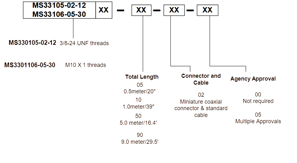
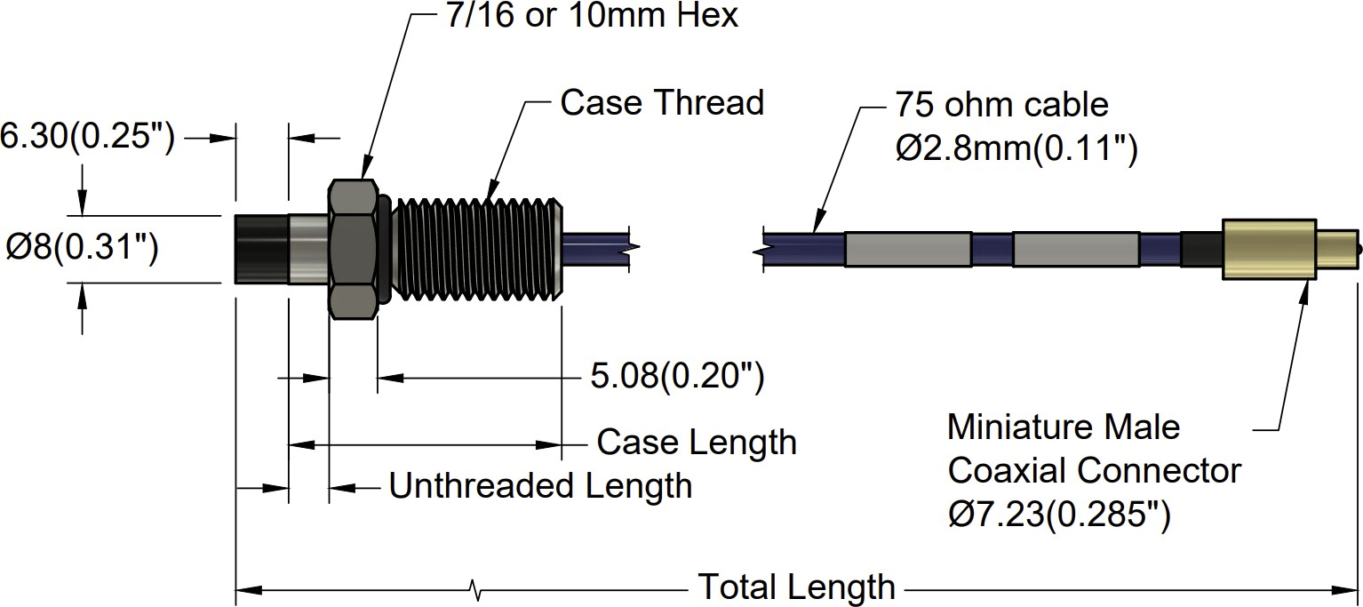
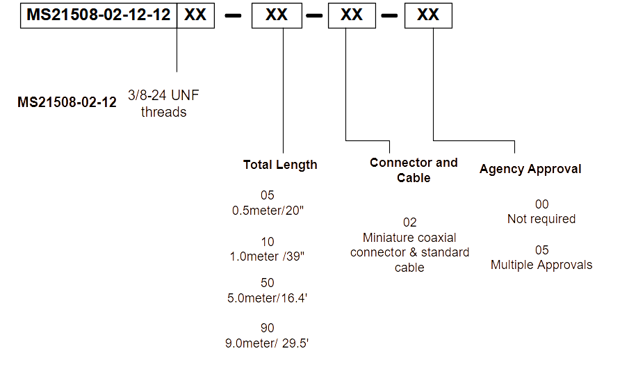
Reverse Mount
| Model | AA: Total Length | BB: Connector & Cable Type | CC: Agency Approval |
| MS330105-02-12-AA-BB-CC ⅜-24 UNF threads |
05 0.5 meter/20 in |
01 = Miniature coaxial connector, connector protector & standard cable | 00 = Not Required |
| MS330106-05-30-AA-BB-CC M10 X 1 threads |
10 1.0 meter/39 in |
02 = Miniature coaxial connector & standard cable | 05 = Multiple Approvals |
| 50 5.0 meter/16.4 feet |
|||
| 90 9.0 meter/29.5 feet |
Extension Cable
| Model | AA: Cable Length | BB: Connector & Cable Type | CC: Agency Approval |
| MS330130 | 05 0.5 meter/20 in |
00 = No stainless steel armor. | 00 = Not Required |
| 10 1.0 meter/39 in |
01 = Stainless steel armor & FEP Jacket. | 05 = Multiple Approvals | |
| 50 5.0 meter/16.4 feet |
02 = Stainless steel armor, no FEP Jacket | ||
| 90 9.0 meter/29.5 feet |
3300 11mm Specifications and Dimensions
Imperial

Metric
Extension Cables
Electrical
Linear Range:
4.0 mm (160 mils). Linear range begins at 0.50 mm (20 mils) from target and is from 0.50 to 4.50 mm (20 to 180 mils)
Incremental Scale Factor (ISF):
3.94 V/mm (100 mV/mil) +/-10% error (including interchangeability error) when measured in 10 mil increments when measured in increments of 0.50 mm (20 mils) over the 4.0 mm (160 mils) linear range
Deviation from best fit straight line (DSL):
1 to 5 meter system length is less than ±0.10 mm (±4 mil).
9 meter system length is less than ±0.15 mm (±6 mil).
Frequency response:
0 to 10kHz (-3 dB) typical, with up to 100 meters (300 feet) of field wiring.
Target Size:
Minimum flat: 30.5 mm (1.2 in) diameter
Minimum perpendicular to shaft 150mm (6 in.)
Mechanical
Probe Tip Material:
Polyphenylene sulfide (PPS).
Probe Case Material:
AISI 303 or 304 stainless steel (SST).
Probe Cable Specifications:
75 Ω coaxial, fluoroethylene propylene (FEP) insulated probe cable in the following total probe lengths: 0.5, 1, 5, or 9 meters.
Extension Cable Material:
75 Ω coaxial, fluoroethylene propylene (FEP) insulated.
System Length:
1 (probe only), 5 or 9 meters including extension cable
Extension Cable Armor (optional):
Flexible AISI 302 SST with/without FEP outer jacket.
Tensile Strength (maximum rated):
220 N (50 lb) probe case to probe lead. 220 N (50 lb) at probe lead to extension cable connectors. 220 N (50 lb) probe case to stainless steel armor.
Connector material:
Gold-plated brass
Recommended Connector Torque:
Hand tightened
Maximum torque:
0.56 N• m (5 in• lb)
Minimum bend Radius (with or without SS armor):
25.4 mm (1.0 in)
Environmental Limits
Probe Temperature Range
Operating Temperature:
-34°C to +177°C (-30°F to +350°F)
Storage Temperature:
-51°C to +177°C (-60°F to +350°F)
Extension Cable Temperature Range
Operating and Storage Temperature:
-51°C to +177°C (-60°F to +350°F)
Storage Temperature:
-51°C to +177°C (-60°F to +350°F)
Proximity Sensor Temperature Range
Operating Temperature:
-35°C to +177°C (-31°F to +350°F)
Storage Temperature:
-51°C to +177°C (-60°F to +350°F)
Relative Humidity:
100% condensing, non-submersible when connectors are protected
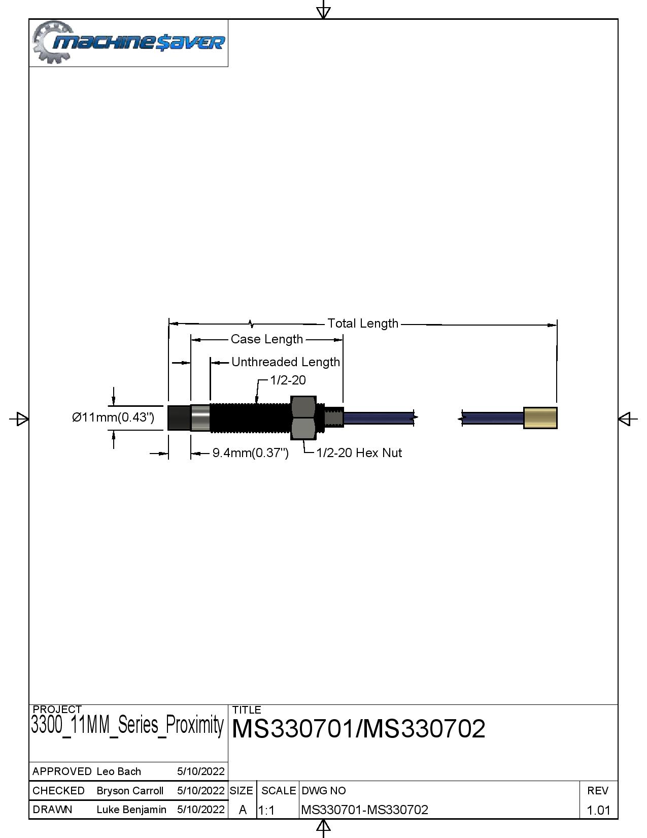
3300 11mm Ordering
Imperial/US
| Model | AA: Unthreaded Length | BB: Overall Case Length | CC: Total Length | DD: Connector & Cable Type | EE: Agency Approval |
| MS330701-AA-BB-CC-DD-EE 1/2-20 UNF thread, no armor |
Order in increments of 0.5 in | Order in increments of 0.5 in |
05 = 0.5 meter/20 in |
01 = Miniature coaxial connector, connector protector & standard cable |
00 = Not Required |
| MS330702-AA-BB-CC-DD-EE 1/2-20 UNF thread, with armor |
Example: 05 = 0.5 in | Example: 35 = 3.5 in |
10 = 1.0 meter/39 in |
02 = Miniature coaxial connector & standard cable |
05 = Multiple Approvals |
| MS330707-AA-BB-CC-DD-EE 5/8-18 UNF thread, no armor |
Minimum unthreaded length: 0.0 in | Minimum unthreaded length: 0.8 in |
50 = 5.0 meter/16.4 feet |
||
| MS330708-AA-BB-CC-DD-EE 5/8-18 UNF thread, with armor |
Maximum unthreaded length: 9.9 in | Maximum unthreaded length: 9.9 in |
90 = 9.0 meter/29.5 feet |
Metric
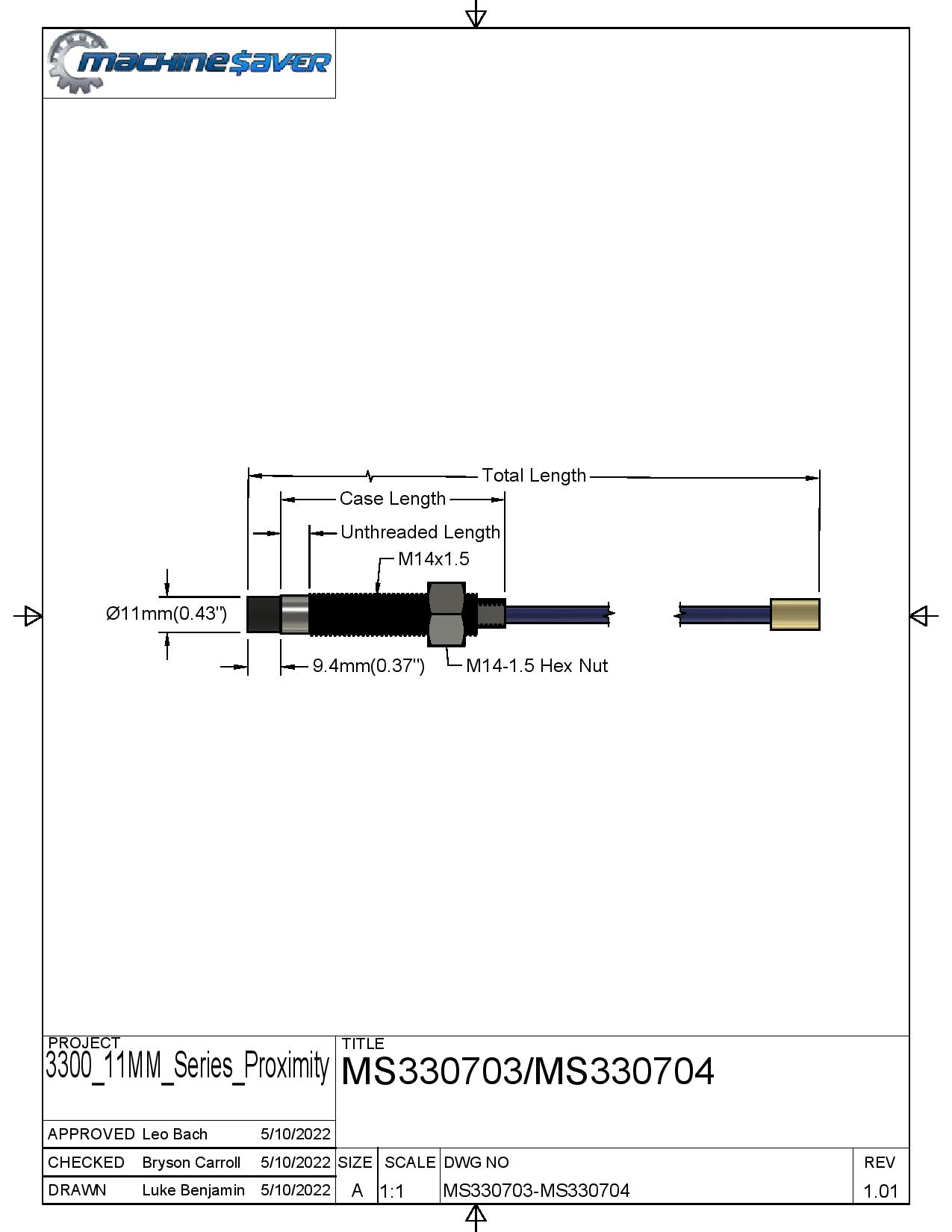
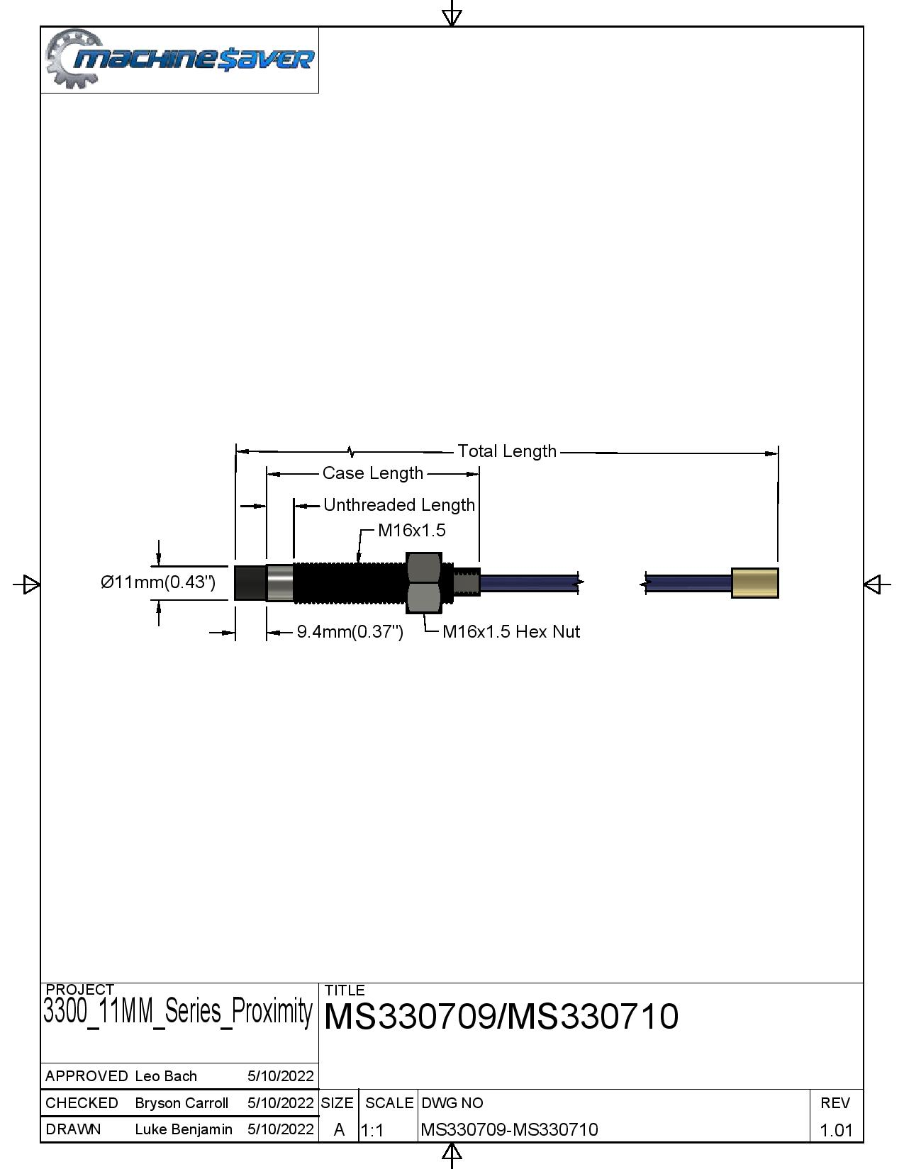
| Model | AA: Unthreaded Length | BB: Overall Case Length | CC: Total Length | DD: Connector & Cable Type | EE: Agency Approval |
| MS330703-AA-BB-CC-DD-EE M14 x 1.5 thread, no armor |
Order in increments of 10 mm | Order in increments of 10 mm |
05 = 0.5 Meter/20 in |
01 = Miniature coaxial connector, connector protector & standard cable |
00 = Not Required |
| MS330704-AA-BB-CC-DD-EE M14 x 1.5 thread, with armor |
Example: 06 = 60 mm | Example: 06 = 60 mm |
10 = 1.0 meter/39 in |
02 = Miniature coaxial connector & standard cable |
05 = Multiple Approvals |
| MS330709-AA-BB-CC-DD-EE M16 x 1.5 thread, no armor |
Minimum unthreaded length: 0 mm | Minimum unthreaded length: 20 mm |
50 = 5.0 meter/16.4 feet |
||
| MS330710-AA-BB-CC-DD-EE M16 x 1.5 thread, no armor |
Maximum unthreaded length: 230 mm | Maximum unthreaded length: 250 mm |
90 = 9.0 meter/29.5 feet |
|
Reverse Mount
| Model | AA: Total Length | BB: Connector & Cable Type | CC: Agency Approval |
| MS330705-02-18-AA-BB-CC ⅜-24 UNF threads |
05 = 0.5 meter/20 in | 01 = Miniature coaxial connector, connector protector & standard cable | 00 = Not Required |
| MS330706-05-46-AA-BB-CC M10 X 1 threads |
10 = 1.0 meter/39 in |
02 = Miniature coaxial connector & standard cable | 05 = Multiple Approvals |
| 50 = 5.0 meter/16.4 feet | |||
| 90 = 9.0 meter/29.5 feet |
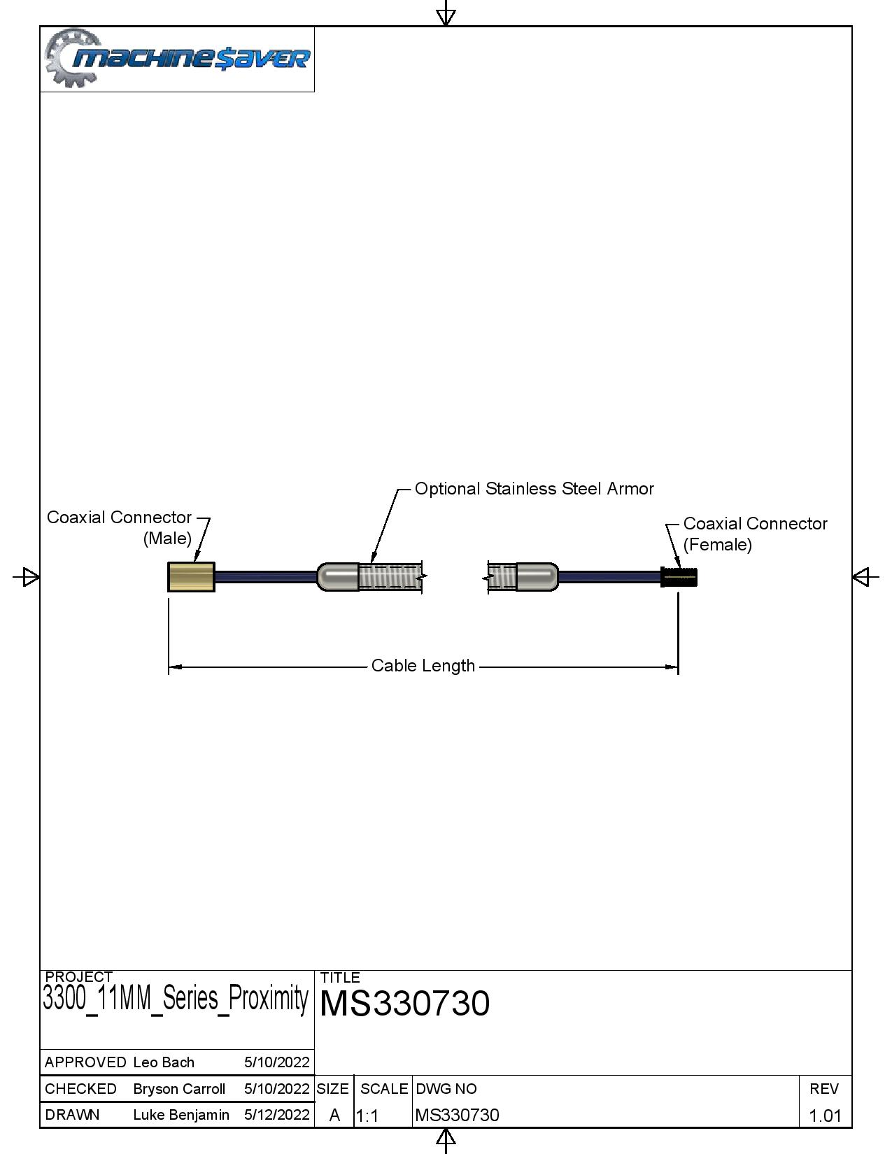
Extension Cable
| Model | AA: Cable Length | BB: Connector & Cable Type | CC: Agency Approval |
| MS330730 | 05 0.5 meter/20 in |
00 = No stainless steel armor. | 00 = Not Required |
| 10 1.0 meter/39 in |
01 = Stainless steel armor & FEP Jacket. | 05 = Multiple Approvals | |
| 50 5.0 meter/16.4 feet |
02 = Stainless steel armor, no FEP Jacket | ||
| 90 9.0 meter/29.5 feet |
3000 Series
3000 Specifications and Dimensions
|
Parameter |
Value |
|
Linear Range |
0.190” 1.43 mm (45 mils) Linear range begins at 0.25 mm (10 mils) to 1.40 mm (55 mils) 0.300” 1.53 mm (60 mils) Linear range begins at 0.25 mm (10 mils) to 1.78 mm (70 mils) |
Incremental Scale Factor (ISF)
|
7.87 V/mm (200 mV/mil) +/-10% error (including interchangeability error) when measured in 10 mil increments when measured in increments of 0.25 mm (10 mils) over the linear range. |
|
Deviation from best fit straight line (DSL) |
15 ft. system length is less than ±0.05 mm (±2 mil). 20 ft. system length is less than ±0.076 mm (±3 mil). |
|
Frequency response |
0 to 10kHz (-3 dB) typical, with up to 100 meters (300 feet) of field wiring |
|
Target Size |
Minimum flat: 25 mm (1.0 in) diameter Minimum perpendicular to shaft 50mm (2 in.) Recommended perpendicular to shaft 75mm (3 in.) |
|
Probe Tip Material |
Polyphenylene sulfide (PPS). |
|
Probe Cable Specifications |
50 Ω coaxial, fluoroethylene propylene (FEP) insulated probe cable |
|
Probe Case Material |
AISI 303 or 304 stainless steel (SST). |
|
Extension Cable Material |
95 Ω coaxial, fluoroethylene propylene (FEP) insulated extension cable |
|
System Length |
15 ft or 20 ft. |
|
Extension Cable Armor (optional) |
Flexible AISI 302 SST with/without FEP outer jacket. |
|
Tensile Strength (maximum rated) |
220 N (50 lb) probe case to probe lead. 220 N (50 lb) at probe lead to extension cable connectors. 220 N (50 lb) probe case to stainless steel armor. |
|
Connector material |
Gold-plated brass |
|
Recommended Connector Torque |
Hand tightened |
|
Maximum torque |
0.56 N• m (5 in• lb) |
|
Minimum bend Radius (with or without SS armor) |
25.4 mm (1.0 in) |


Electrical
Linear Range:
0.190” 1.43 mm (45 mils) Linear range begins at 0.25 mm (10 mils) to 1.40 mm (55 mils)
0.300” 1.53 mm (60 mils) Linear range begins at 0.25 mm (10 mils) to 1.78 mm (70 mils)
Incremental Scale Factor (ISF):
7.87 V/mm (200 mV/mil) +/-10% error (including interchangeability error) when measured in 10
mil increments when measured in increments of 0.25 mm (10 mils) over the linear range.
Deviation from best fit straight line (DSL):
15 ft. system length is less than ±0.05 mm (±2 mil).
20 ft. system length is less than ±0.076 mm (±3 mil).
Frequency response:
0 to 10kHz (-3 dB) typical, with up to 100 meters (300 feet) of field wiring.
Target Size:
Minimum flat: 25 mm (1.0 in) diameter
Minimum perpendicular to shaft 50mm (2 in.)
Recommended perpendicular to shaft 75mm (3 in.)
Mechanical
Probe Tip Material:
Polyphenylene sulfide (PPS).
Probe Case Material:
AISI 303 or 304 stainless steel (SST).
Probe Cable Specifications:
50 Ω coaxial, fluoroethylene propylene (FEP) insulated probe cable.
Extension Cable Material:
95 Ω coaxial, fluoroethylene propylene (FEP) insulated extension cable.
System Length:
15 ft or 20 ft.
Extension Cable Armor (optional):
Flexible AISI 302 SST with/without FEP outer jacket.
Tensile Strength (maximum rated):
220 N (50 lb) probe case to probe lead. 220 N (50 lb) at probe lead to extension cable connectors. 220 N (50 lb) probe case to stainless steel armor.
Connector material:
Gold-plated brass.
Recommended Connector Torque:
Hand-tightened.
Maximum torque:
0.56 N• m (5 in• lb).
Minimum bend Radius (with or without SS armor):
25.4 mm (1.0 in).
Environmental Limits
Probe Temperature Range
Operating Temperature:
-34°C to +125°C (-30°F to +257°F)
Storage Temperature:
-51°C to +125°C (-60°F to +257°F)
Extension Cable Temperature Range
Operating and Storage Temperature:
-51°C to +125°C (-60°F to +257°F).
Storage Temperature:
-51°C to +125°C (-60°F to +257°F).
Proximity Sensor Temperature Range
Operating Temperature:
-35°C to +125°C (-31°F to +257°F).
Storage Temperature:
-51°C to +125°C (-60°F to +257°F).
Relative Humidity:
100% condensing, non-submersible when connectors are protected.
3000 Ordering
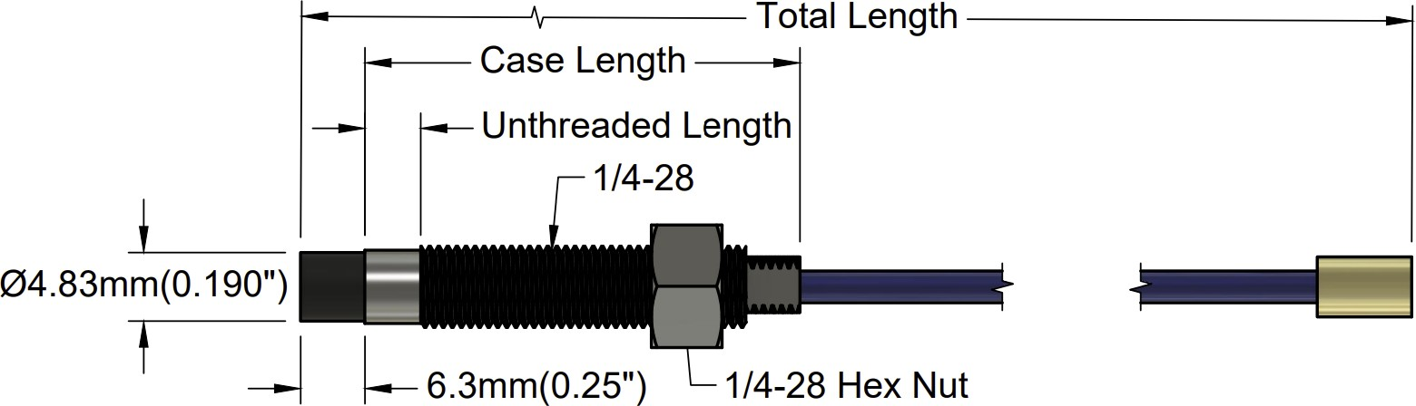
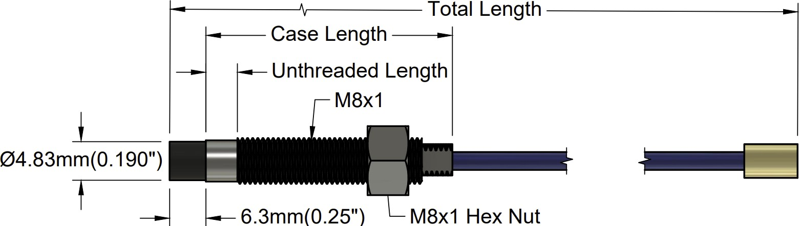
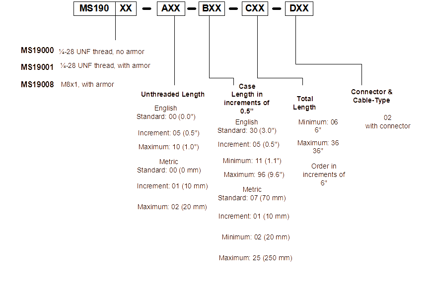
3000 Series, 190 Probes
| Model | AA: Unthreaded Length | BB: Overall Case Length | CC: Total Length | DD: Connector & Cable Type |
| MS19000 ¼-28 UNF thread, no armor |
English |
English |
Minimum: 06 |
02 with connector |
| MS19001 ¼-28 UNF thread, with armor |
Standard: 00 (0.0 in.) |
Standard: 30 (3.0 in.) |
Maximum: 36 |
|
| MS19007 M8x1, no armor |
Increment: 05 (0.5 in.) | Increment: 05 (0.5 in.) | Increment: of 6 in | |
| MS19008 M8x1, with armor |
Minimum: 00 (0.0 in.) | Minimum: 11 (1.1 in.) | ||
| Maximum: 10 (1.0 in.) | Maximum: 96 (9.6 in.) | |||
| Metric |
Metric |
|||
| Standard: 00 (0 mm) | Standard: 07 (70 mm) | |||
| Increment: 01 (10 mm) | Increment: 01 (10 mm) | |||
| Minimum: 00 (0.0 mm) | Minimum: 02 (20 mm) | |||
| Maximum: 02 (20 mm) | Maximum: 25 (250 mm) |
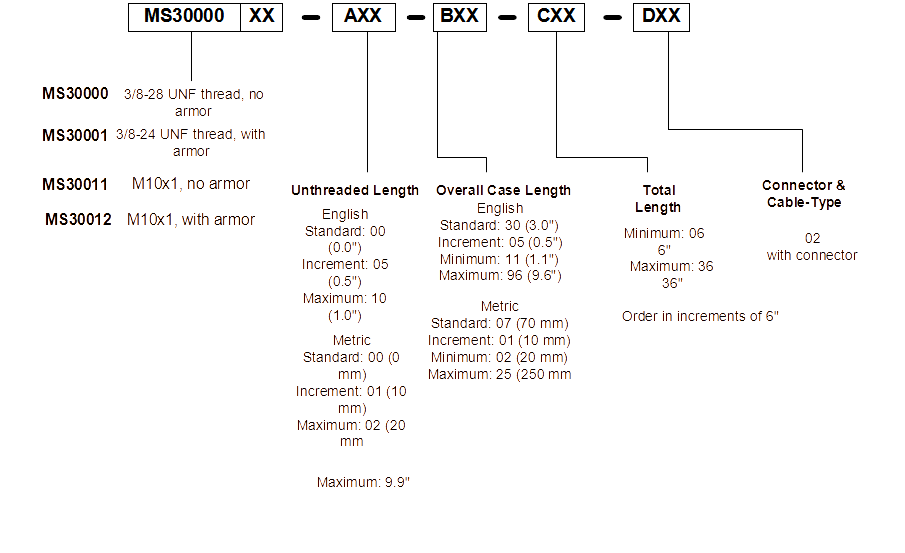
3000 Series, 300 Probes
| Model | AA: Unthreaded Length | BB: Overall Case Length | CC: Total Length | DD: Connector & Cable Type |
| MS30000 ⅜-28 UNF thread, no armor |
English |
English |
Minimum: 06 |
02 with connector |
| MS30001 ⅜-24 UNF thread, with armor |
Standard: 00 (0.0 in.) |
Standard: 30 (3.0 in.) |
Maximum: 36 |
|
| MS30011 M10x1, no armor |
Increment: 05 (0.5 in.) | Increment: 05 (0.5 in.) | Increment: of 6 in | |
| MS30012 M10x1, with armor |
Minimum: 00 (0.0 in.) | Minimum: 11 (1.1 in.) | ||
| Maximum: 10 (1.0 in.) | Maximum: 96 (9.6 in.) | |||
| Metric |
Metric |
|||
| Standard: 00 (0 mm) | Standard: 07 (70 mm) | |||
| Increment: 01 (10 mm) | Increment: 01 (10 mm) | |||
| Minimum: 00 (0.0 mm) | Minimum: 02 (20 mm) | |||
| Maximum: 02 (20 mm) | Maximum: 25 (250 mm) |
Extension Cable
| Model | AA: Cable Length |
|
MS2789-AXXX no armor |
108 = 108 in / 9 ft |
|
MS4454-AXXX with armor |
120 = 120 in / 10 ft |
| 132 = 132 in / 11 ft | |
| 144 = 144 in / 12 ft | |
| 156 = 156 in / 13 ft | |
| 168 = 168 in / 14 ft | |
| 180 = 180 in / 15 ft | |
| 192 = 192 in / 16 ft | |
| 204 = 204 in / 17 ft |
7200 Series
7200 Specifications and Dimensions
Specifications
|
Parameter |
Value |
|
Linear Range |
2.0 mm (80 mils). Linear range begins at 0.38 mm (15 mils) from target and is from 0.38 to 2.41 mm (15 to 95 mils) |
Incremental Scale Factor (ISF)
|
7.87 V/mm (200 mV/mil) +/-4% error when measured in 10 mil increments when calibrated as a system. Error is 9.5% including interchangeability error when measured in increments of 0.25 mm (10 mils) over the 2.0 mm (80 mils) linear range |
|
Deviation from best fit straight line (DSL) |
Less than ±0.06 mm (± 2.3 mils). |
|
Frequency response |
0 to 10kHz (-3 dB) typical, with up to 100 meters (300 feet) of field wiring. |
|
Target Size |
Minimum: 24 mm (1.0 in) diameter. |
|
Probe Tip Material |
Polyphenylene sulfide (PPS). |
|
Probe Cable Specifications |
75 Ω coaxial, fluoroethylene propylene (FEP) insulated probe cable in the following total probe lengths: 0.5, 1, 5, or 9 meters |
|
Probe Case Material |
AISI 304 stainless steel (SST) |
|
Extension Cable Material |
75 Ω coaxial, fluoroethylene propylene (FEP) insulated. |
|
System Length |
5 or 7 meters including extension cable |
|
Extension Cable Armor (optional) |
Flexible AISI 302 SST with/without FEP outer jacket. |
|
Tensile Strength (maximum rated) |
220 N (50 lb) probe case to probe lead. 220 N (50 lb) at probe lead to extension cable connectors. 220 N (50 lb) probe case to stainless steel armor |
|
Connector material |
Gold-plated brass |
|
Recommended Connector Torque |
Hand tightened |
|
Maximum torque |
0.56 N• m (5 in• lb) |
|
Minimum bend Radius (with or without SS armor) |
25.4 mm (1.0 in) |
|
Probe Temperature Range Operating Temperature |
-34°C to +125°C (-30°F to +257°F) |
|
Storage Temperature |
-51°C to +125°C (-60°F to +257°F) |
|
Extension Cable Operating and Storage Temperature |
-51°C to +177°C (-60°F to +351°F) |
|
Relative Humidity |
100% condensing, non-submersible when connectors are protected |
Imperial


Metric
Reverse Mount
Extension Cables