Mounting Locations and Methods
- Installation Tools
- Imperial/US Drill + Tap (Best Method for Frequency Response)
- Metric Drill + Tap (Best Method for Frequency Response)
- Epoxy + Mounting Pad, Phenolic Block, or Motor Fin Mount
- Magnetic Mounting Pad
Installation Tools
Required Tools
-
-
-
-
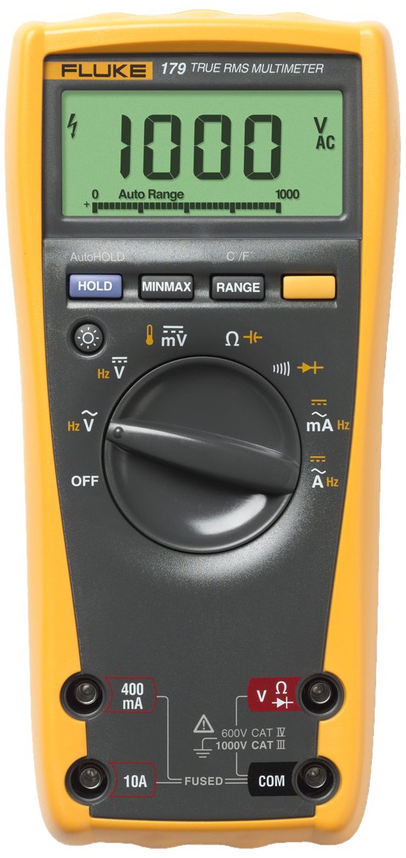
- Multimeter (Fluke 179 True RMS Multimeter Recommended)

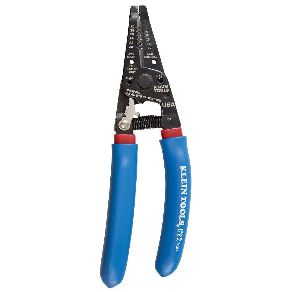
- Wire/Cable Strippers (16-26 AWG Stranded Recommended)

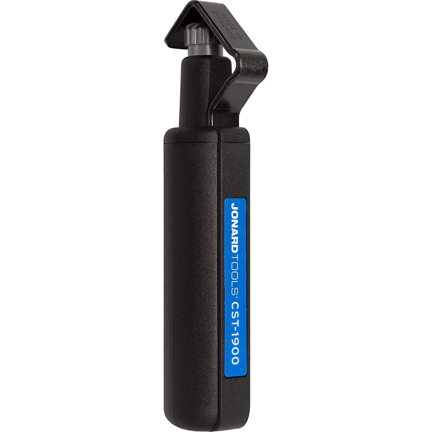
- Cable Jacket Remover (Jonard Recommended)

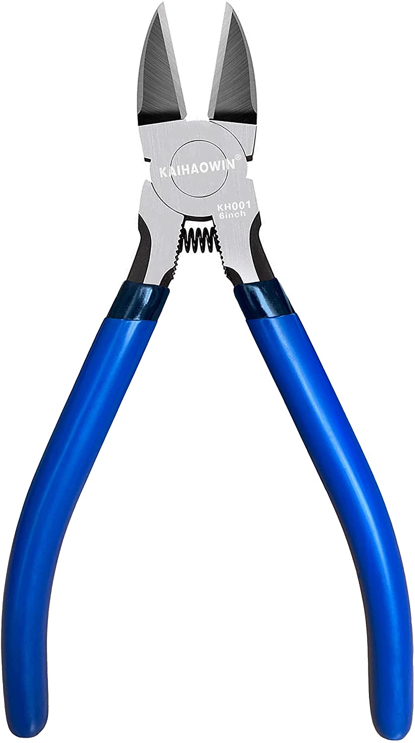
- Flush Cutter or Lineman's/Cutting Pliers

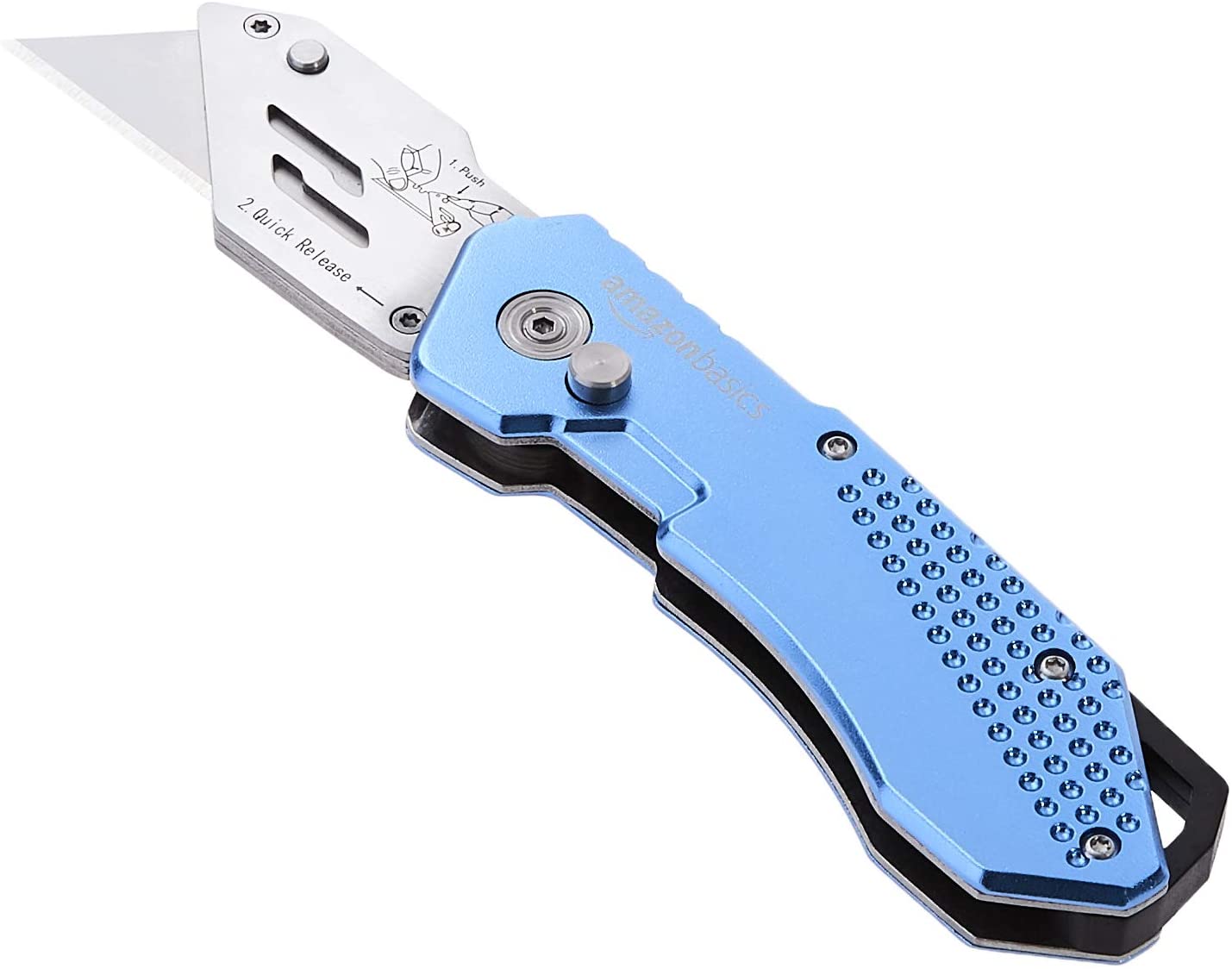
- Blade/Boxcutter/Scalpel

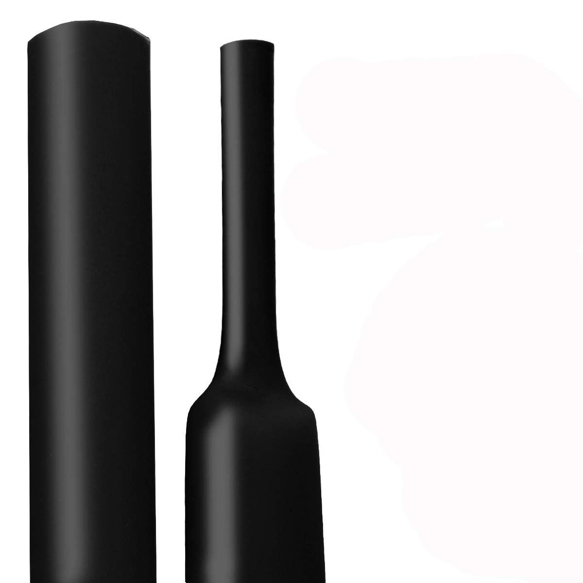
- Adhesive Lined, 1/2" Heatshrink Tubing, 3-1 Shrink Ratio

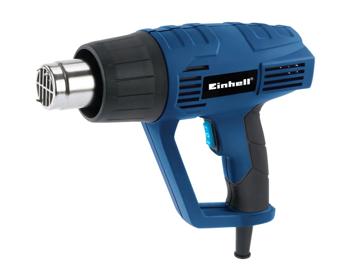
- Heat gun / Heat source

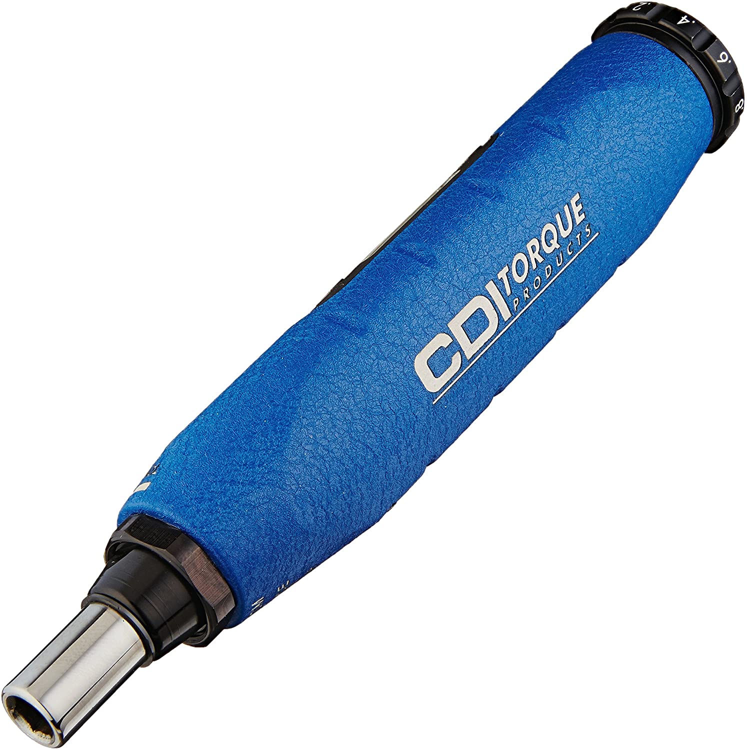
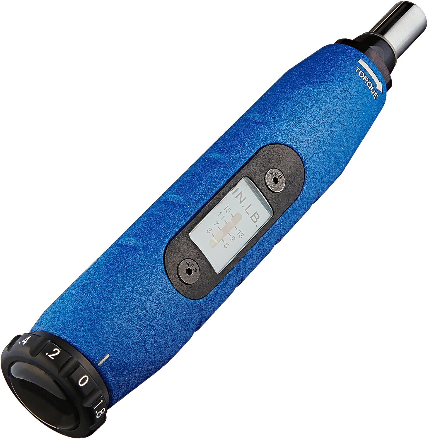
- Metric Allen Torque Wrench | 3/16" Torque-Adjustable Hex Key


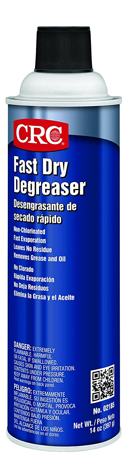
- Degreasing Kit + Shop Towels


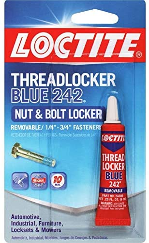
- Locktite Blue 242 Threadlocker

- Multimeter (Fluke 179 True RMS Multimeter Recommended)
-
-
-

Tools By Mounting Method
Metric Captive Bolt | Standard Captive Bolt
-
-
-
-
- Metric Bottoming Tap M6x1 | Standard Bottoming 1/4"-28 UNF Tap


- 5.0mm (13/64") Drill Bit | #3 drill bit (7/32”)
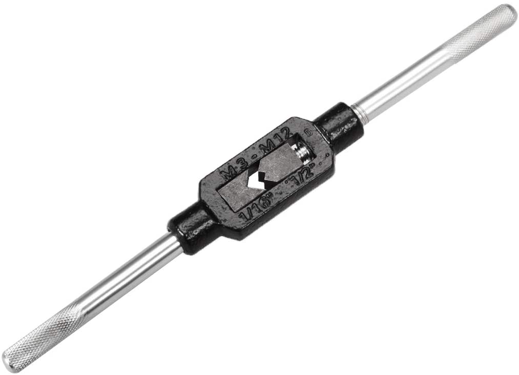
- Tap Handle

- Power Drill (We Recommend Wired and 1/2")
Note that the amp and torque requirements to cut into the case of a machine differs by case material. Select accordingly.

- Metric Bottoming Tap M6x1 | Standard Bottoming 1/4"-28 UNF Tap
-
-
-


Mounting Pad | Frenolic Block (High Heat) | Motor Fin Mount
-
-
-
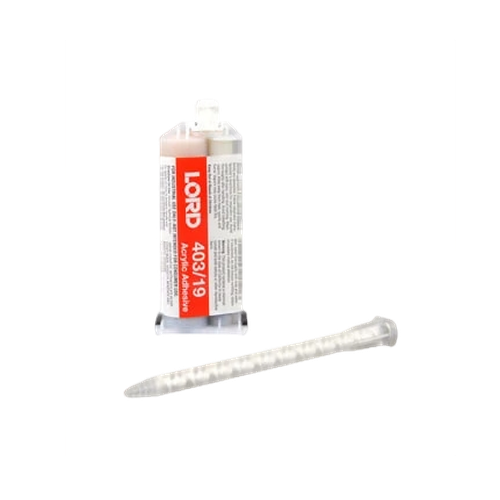
- Epoxy Cartridge (50ml LORD® 403/19 Modified Acrylic Adhesive Recommended)
Note that each 50ml cartridges contain enough epoxy to mount:
~3 Mounting Pads
~2 Frenolic Blocks
~2 Motor Fin Mounts
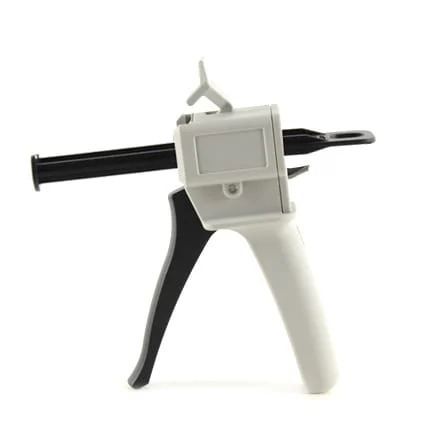
- Epoxy 4-1 Ratio Plunger (Compatible with Recommended Gun + Cartridge)

- Epoxy Gun

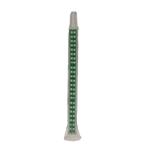
- Extra Mixer Nozzles
Note that the extra nozzles are optional but the epoxy will set within 15 minutes of sitting. If you plan to take more than 5 minutes to use the whole cartridge, you should plan on replacing the nozzle.

- Epoxy Cartridge (50ml LORD® 403/19 Modified Acrylic Adhesive Recommended)
-
-

Magnetic Mounting Pad
-
-
-
- No Additional Tools Required. Can be installed using just the required tools.
Use caution when placing the magnet on the machine. Read the mounting specific instructions before installing to avoid hurting yourself or damaging your sensors.
- No Additional Tools Required. Can be installed using just the required tools.
-
-
Bus Communication Verification Tools
Note that this section is specific to customers who want to use a more robust, but also more labor intensive, method to verify their RS485 Electrical Characteristics and Modbus Communications.
Imperial/US Drill + Tap (Best Method for Frequency Response)
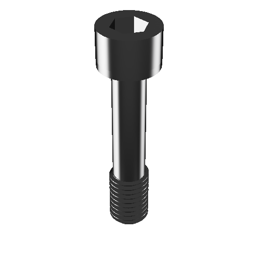
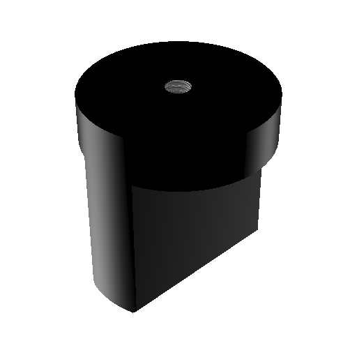
Captive Mounting Bolt 1/4"-28
Tools Required
- Power Drill
- 3/16" Allen Wrench/Hex Key
- #3 drill bit (7/32”)
- UNF 1/4"-28 Steel Tap, 3-4 Flute, Right-Hand Thread
- Captive 1/4"-28 Mounting Bolt
- Loctite Threadlocker 242 (Blue/Removable)
- Torque Wrench
Procedure
- Choose mounting location. Accelerometer/Sensor Mounting Location Selection
- Verify the machine casing is thick enough to drill 0.3 inches (7.65mm).
If the casing is not thick enough, choose a different mounting method. - Use the #3 drill bit (7/32”) to drill into the machine casing 0.3 inches (7.65mm).
The hole should be perpendicular to the face of the machine. -
Make sure to drill a straight hole. Crooked holes can result in convolution of the triaxial signals.
- Use the UNF 1/4"-28 tap to cut the threads into the drilled hole.
Be sure to keep the tap perpendicular to the face of the machine while tapping to avoid a crooked thread. - After tapping completely to the bottom of the 0.3 inches (7.65mm), clean any metal shavings from the hole and clean with a Q-Tip and degreaser.
- Insert 3/16" Allen Wrench/Hex Key into the hex depression on the captive 1/4"-28 mounting bolt.
- Screw the 1/4"-28 mounting bolt into the TriVibe, starting on the LED side.
When completely inserted, the threaded tip of the mounting bolt should stick out of the backside of the TriVibe. - Add a dab of Loctite Threadlocker 242 to the exposed threads.
-
This step is important because, over time, movement can cause the mounting bolts to become loose and result in improper vibration levels.
- Insert the wet, loctite-ed threads into the newly tapped hole.
- Rotate the Allen Wrench/Hex Key clockwise to tighten until the torque on the Allen wrench is 25.0 lb-in (3.0 N-m).
-
DO NOT OVER TIGHTEN. Excess force can damage the TriVibe.
Metric Drill + Tap (Best Method for Frequency Response)
Captive Mounting Bolt M6-1

Tools Required
- Power Drill
- 5.0mm Allen Wrench/Hex Key
- 5.0mm (13/64") Drill Bit
- ANSI M6x1 Steel Tap, 3-4 Flute, Right-Hand Thread
- Captive M6-1 Mounting Bolt
- Loctite Threadlocker 242 (Blue/Removable)
- Torque Wrench
Procedure
- Choose mounting location. Accelerometer/Sensor Mounting Location Selection
- Verify the machine casing is thick enough to drill in 7.65mm (0.3 inches).
If the casing is not thick enough, choose a different mounting method. - Use the 5.0mm (13/64") drill bit to drill into the machine casing 7.65mm (0.3 inches).
The hole should be perpendicular to the face of the machine. - Use the ANSI M6-1 tap to cut the threads into the drilled hole. Be sure to keep the tap perpendicular to the face of the machine while tapping to avoid a crooked thread.
- After tapping completely to the bottom of the 7.65mm (0.3 inches), clean any metal shavings from the hole and clean with a Q-Tip and degreaser.
- Insert 5.0mm Allen Wrench/Hex Key into the hex depression on the captive M6-1 mounting bolt.
- Fasten the 1/4"-28 captive mounting bolt into the center threads of the TriVibe, starting on top of the sensors (the side with an LED).
When completely inserted, the threaded tip of the mounting bolt should stick out the bottom of the TriVibe (opposite sied of the LED. - Add a dab of Loctite Threadlocker 242 to the exposed threads.
-
This step is important because, over time, movement can cause the mounting bolts to become loose and result in improper vibration levels.
- Insert the wet, loctite-ed threads into the newly tapped hole.
- Rotate the Allen Wrench/Hex Key clockwise to tighten until the torque on the Allen wrench is 25.0 lb-in (3.0 N-m).
-
Do not over tighten because excess external pressure/force on the housing can cause damage to the internal chops and sensors of TriVibe.
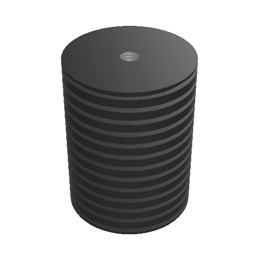
Epoxy + Mounting Pad, Phenolic Block, or Motor Fin Mount
Mounting Hardware

Instructions
-
After reading about the various mounting options and selecting a location that suits your machine application.
-
To remove all debris/dust/grease and ensure a strong bond between the mounting hardware and the metal of the machine or component, use a contact cleaner solution to clean the following:
- The mounting hardware itself.
-
The selected mounting location where the mounting hardware will contact the machine or component.
-
Locations where the curing tape will contact the machine.
-
Allow time for the contact cleaner to dry completely OR wipe clear any residual cleaner using clean shop towels.
-
Depress the black plunger of the epoxy kit to force 15ml (roughly 1/3 of the 50ml cartridge) of epoxy, through the mixing nozzle.
-
Use a tongue depressor or similar clean mixing tool to vigorously and thoroughly mix the epoxy for 30 seconds in the disposable cup. From the moment the epoxy begins mixing through the nozzle to the installation of the mounting hardware there is 2 to 4 minutes of working time @ 75°F (24°C). So Step #7 should be completed by the 4th minute.
The tip of the nozzle may also be used, in lieu of a tongue depressor, to mix the epoxy in the disposable cup.
-
Apply the epoxy to the flat side of the mounting hardware.
Be careful not to get ANY epoxy on the bolt threads or in the threaded hole while handling the sensor.
- Press the mounting hardware down on the selected mounting location. There should be enough epoxy under the mounting hardware that it pools around the edges when it is pressed down.
- Use a liberal amount of curing tape to hold the mounting hardware in place while the epoxy cures. Allow a full 10 minutes for the epoxy to cure before installing the sensor and the sensor mounting bolt. For best results, verify that nothing puts additional pressure on the sensor or mounting hardware for a full 24 hours @ room temperature, or shorter periods at higher temperatures, while the epoxy is reaching its fully cured state.
To reduce the cure time, a heat gun may be used. Hold the heat gun 4-6 inches from the epoxy while employing a gentle sweeping motion around the mounting hardware base to uniformly heat the epoxy for 10-15 minutes.
- Tighten the sensor down into the tapped hole of the mounting hardware using the instructions from the imperial/us or metric mounting bolt instructions.
Magnetic Mounting Pad
Magnetic Mounting Pad
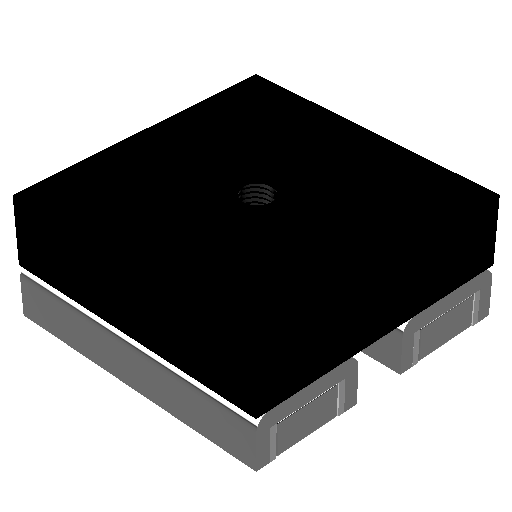 The magnet mounting pad is 120 lb pull force and dimensions length 2 in, width 2 in, and height 7/8 in. Also, it has a 1/4x28” UNF mounting connection.
- Choose sensor mounting location (Sensor should be mounted perpendicular to the shaft).
- Clean the desired sensor mounting location to allow the magnet to have the best connection with the machine casing.
- Attach the TriVibe to the mounting magnet.
- Use a rolling motion to roll the magnet & TriVibe onto the machine! DO NOT just plop it on the machine as this could damage the internal accelerometers. CAUTION: keep fingers off of the silver on the magnet while attaching to machine, the force of the magnet is strong enough to seriously injure a person.