TriVibe
TriVibe is an industrial predictive maintenance product for collecting and analyzing tri-axial vibration and temperature data in machinery. It has a Modbus RTU Slave interface for easy integration into industrial automation systems. TriVibe captures three-axis vibration data in acceleration and velocity units, with RAW waveform and spectral data. It is CSA certified for hazardous areas Class 1 Div 2, has self-calibration verification, and can be daisy-chained to reduce installation costs. The device has internal sensor alarms for vibration and temperature, and all functions and settings are configurable via Modbus registers. With configurable sample rates, TriVibe allows for customized data analysis to meet specific industrial needs, making it a popular choice for serious vibration analysis companies and data scientists.
- Sensor Overview
- System Wiring
- TriVibe Field Cable Options
- System Layout Diagram (Simplified & Color-Coded)
- T-Port PCB
- T-Port Enclosure Options
- Conduit Recommendations
- Mounting Locations and Methods
- Installation Tools
- Imperial/US Drill + Tap (Best Method for Frequency Response)
- Metric Drill + Tap (Best Method for Frequency Response)
- Epoxy + Mounting Pad, Phenolic Block, or Motor Fin Mount
- Magnetic Mounting Pad
- Integration
- Modbus Registers Map
- LED Status
- Jupyter Notebook Setup
- Refactored Analysis Data Capture Code Example
- Analysis Data (Time Waveform & Vibration Spectrum)
- Changing an RTU number / Slave Address
- Modbus Register Highlight (Quick Start)
- Modbus Client
- ITC Wiring Diagram
- Wiring to a PC with DTech USB to RS485 Adapter
Sensor Overview
Brochure


Features & Software
Overview
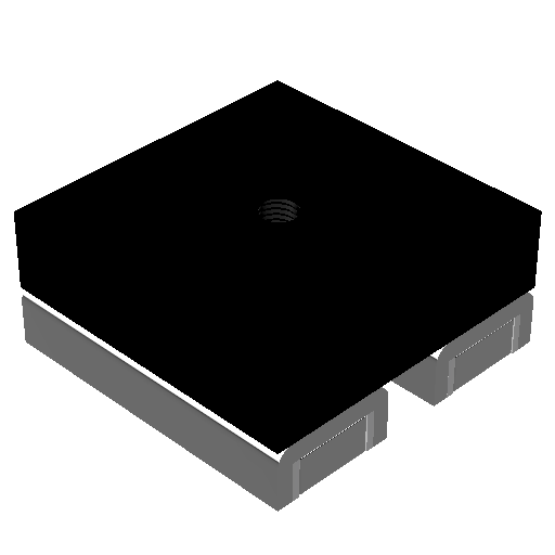
Figure 1: TriVibe Sensor
Machine Saver’s IIOT TriVibe provides the highest resolution vibration data for small antifriction (ball/roller) element bearing machines in the world. The TriVibe gathers information needed for Machine Learning Artificial Intelligence Data with superb resolution for slow and high speed machines all with one universal TriVibe.
TriVibe has the lowest total cost of ownership (TCO) with our unique “wire less” semi-tethered approach which allows 24/7 information gathering, internal calibration verification, no batteries to replace and no lost machine information.
TriVibe delivers multi sensor, multi axis, 50,000+ samples per second via serial Modbus RS485, polling overall vibration and temperature data continuously near real-time. TriVibe is captures the time waveform and spectral FFT data on all axis simultaneously for high resolution machine health information to determine the root cause of the machine anomalies before the problem. The TriVibe paired with our gateway or our edge devices with machine learning algorithms can learn faster and more accurately to automatically diagnose impending machine failures long before they occur.
Layout
Features and Benefits
Maintenance free – no battery to change
No periodic calibration verification required
Acquire spectrum (FFT) data via MODBUS automatically upon an alarm
Easy mounting with small footprint
One cable run between all sensors
1Hz to 8kHz frequency response
Programmable band pass filters
Programmable alarm setpoints
Configurable for impact or mechanical looseness sensing
IP67 (NEMA 6P)
Includes temperature sensor
Compatible Software
Modbus Client - A Graphical User Interface for reading, writing and monitoring Modbus RTU + Modbus TCP.
MachineCloud (Reporting Portal) - Cloud Based System, 24/7 Monitoring by Level 4 Analysts, Simple Maintenance Reports Upon Detection and Verification of Anomaly.
MachineCloud (Analysis Portal) - Cloud Based System for Vibration Analysts, Machine Learning Anomaly Detection Filters, Focused Component-Based Issue Highlighting, Banding Alarms.
Specifications and Dimensions
Specifications
High Frequency Internal Sensor
| Frequency Range |
Axis 1 & Axis 3 - 1.5 Hz to 8000 Hz Axis 2 - 1.5 Hz to 5100 Hz |
| Sensitivity | ~100 mV/g |
| Amplitude Range | 0 to 20 g |
| Sample Rate |
50,000 Samples/Second |
| Overall Filter Range | 1.1 Hz to 6553.4 Hz |
Low Frequency Internal Sensor
| Frequency Range |
All Axes - 1.5 Hz to 1000 Hz |
| Sensitivity | ~800 mV/g |
| Amplitude Range | 0 to 2 g |
| Sample Rate |
50,000 samples/second |
| Overall Filter Range | 1.1 Hz to 6553.4 Hz |
Communication
| Configuration | All Functions Settable via Modbus Read/Write OR Graphical User Interface Software |
| Baud rate | 115,200 bits/second |
|
Byte Size |
8 |
| Parity | None |
| Stop Bits | 1 |
| Handshakes | None |
| Minimum Timeout | 0.100 Seconds |
| Minimum Interpacket Delay | 0.001 Seconds |
Dimensions
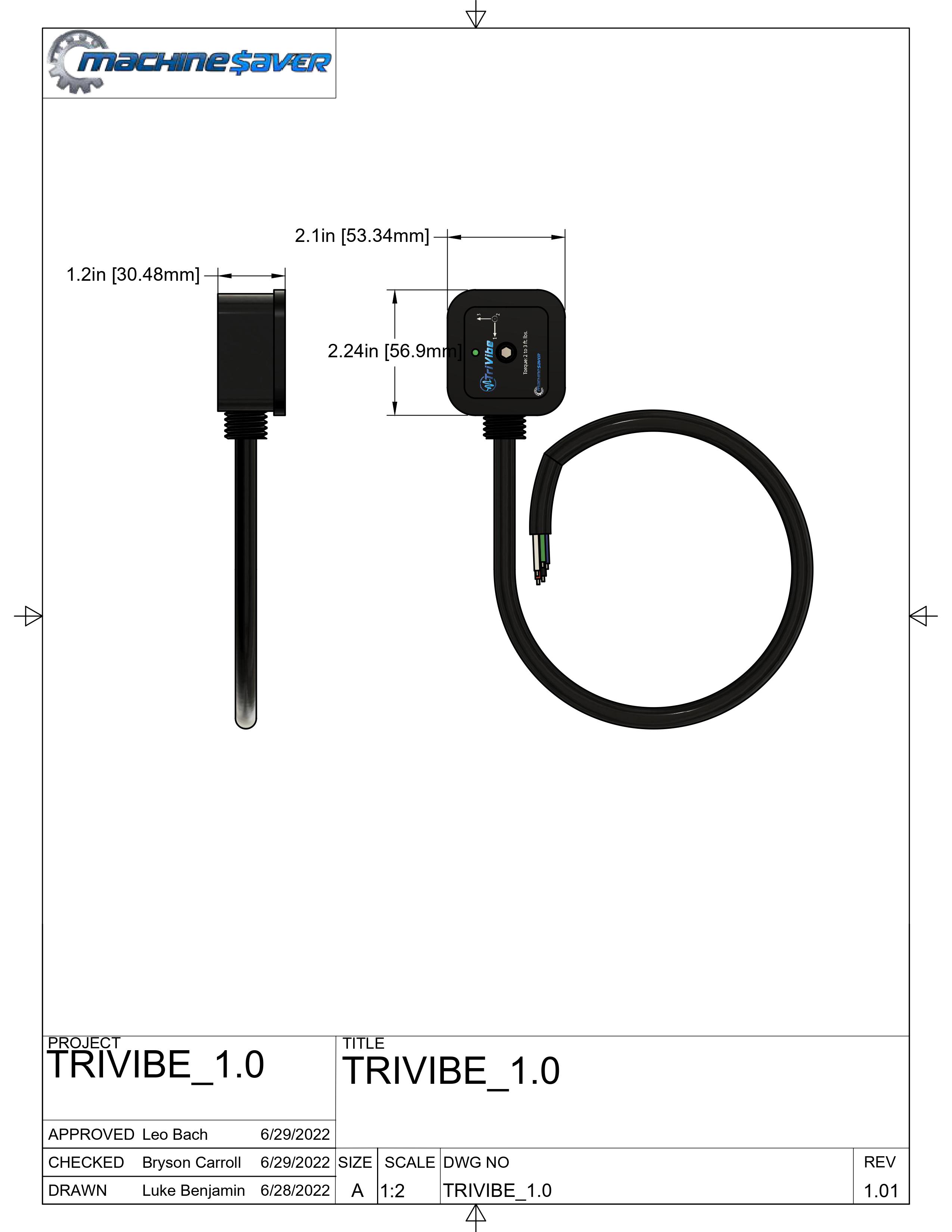
Figure 1: TriVibe Dimensional Drawing.
System Wiring
TriVibe Field Cable Options
We highly recommend using one of the cables that have been vetted by Machine Saver's Engineering Team, if you use a cable that is not specified on our list and have communication issues we may be unable to help you resolve them.
If you still wish to select another cable manufacturer, it is critical to get the following specifications correct:
Power pair of conductors: 18 AWG, twisted pair
Digital Modbus pair of conductors: 22 AWG, twisted pair
The cable capacitance should be low 12pF / foot
The cable impedance should be as close to 120 ohms as possible
There should be a foil shield 100% with a drain wire (overall or surrounding the digital Modbus pair)
| VTB-CBL-10 | VTB-CBL-40 | VTB-CBL-50 | |
| Cable Capacitance (pF/ft) | 11 | 11 | 11 |
|
Impedance (Ohms) |
120 | 120 | 105 |
| Temperature Rating (°C) | -80 to +200 | -40 to +105 | -20 to +80 |
| Power Conductor Pair |
18AWG No Power Pair Shield |
18AWG 100% Foil Shield |
18AWG No Power Pair Shield |
| Weight (lbs/meter) |
0.10 |
0.24 |
0.12 |
| Data (Modbus) Conductor Pair |
22AWG No Data Pair Shield |
22AWG 100% Foil Shield |
22AWG 100% Foil Shield |
| Drain | 24AWG | 24AWG | 24AWG |
| Overall Shield | 100% Foil Shield | 100% Foil Shield | No Overall Shield |
| Outer Jacket Material | FEP (Red or Black) | TPE (Black) | PVC (Black) |
| Outer Jacket Thickness (in) | 0.012 | 0.050 | 0.040 |
| Outer Jacket Dimensions (in) | 0.209 | 0.365 | 0.275 |
| Bend Radius (in) | 2.09 | 3.15 | 2.75 |
| TriVibe Sensor Load | (12) @ 1000 ft with a single power supply. (22) @ 1500 -2000 ft with 2 Power Supplies and Sensor Distribution Dependent. |
(12) @ 1000 ft with a single power supply. (22) @ 1500 -2000 ft with 2 Power Supplies and Sensor Distribution Dependent. |
(12) @ 1000 ft with a single power supply. (22) @ 1500 -2000 ft with 2 Power Supplies and Sensor Distribution Dependent. |
| Certifications | CL2, CMP | UL and CSA Class I Div 2 | UL444, NEC725 & 800 |
| Suitability | Sunlight Resistant, Direct Burial, Wet, Oil, Gas, Abraision, Acid, Indoor | Sunlight Resistant, Direct Burial, Wet, Oil, Abraision, High Stress Movement, Indoor, Outdoor | Sunlight Resistant, Direct Burial, Indoor, Outdoor |
| Cycles | N/A | 5 Million | N/A |
| Cost | $$ | $$$ | $ |
System Layout Diagram (Simplified & Color-Coded)
Proper TriVibe Layout:
- A Modbus Master which has properly designed RS-485 (TIA-485(-A)/EIA-485)
ports with built-in pullup and pulldown resistors enabled to enforce the RS485
(TIA-485(-A)/EIA-485) electrical standard. - A single field cable bus trunk for each RS-485 (TIA-485(-A)/EIA-485) port
available from the Modbus Master. - Each T-Port connection terminal allows a TriVibe Tri-Axial Vibration Sensor to
drop off the field cable bus trunk by way of the integral sensor cable. - On each available RS485 (TIA-485(-A)/EIA-485) port, only the last/furthest T-Port
connection terminal should have a jumper installed, thereby enabling the 120Ω
terminating resistor. - As long as you do not plan to expand with more TriVibe Tri-Axial Vibration
Sensors on a particular field cable bus trunk, It is permissible to use the last set
of terminals of the last/furthest T-Port to connect a TriVibe by way of the integral
sensor cable. - Field cable which adheres to RS-485 (TIA-485(-A)/EIA-485) specification and
Machine Saver's recommended characteristics. - Total length of field cable bus trunk should not exceed 2800 feet (855 meters)
for Modbus Masters communicating at a baudrate of 115,200 bit/s. - 24 - 36 VDC should be verified available to power each TriVibe Tri-Axial Vibration
Sensor at each T-Port connection terminal which includes the T-Port which is
furthest/last on the field cable bus trunk from the Modbus Master.

Improper TriVibe Layout:
- A Modbus Master which has IMPROPERLY designed RS-485 (TIA-485(-A)/EIA-485)
ports. Missing (or disabled) built-in pullup and pulldown resistors leaving the
bias-voltage at an unknown level. - A field cable bus trunk which uses a T-Port connection terminal to attempt to
split the field cable bus trunk, thereby violating the RS-485 (TIA-485(-A)/EIA-485)
electrical communication standard. - The above issue also results in 2 furthest T-Port connection terminals to be
identified, if you attempt this and see there are 2 possible places to install
a jumper AND/OR if you have more than 1 jumper per RS-485 port re-evaluate your
layout. The layout cannot remain in these conditions and function appropriately. - Field cable adheres to RS-485 (TIA-485(-A)/EIA-485) specification and
Machine Saver's recommended field wire chart characteristics. - Total length of field cable bus trunk MUST NOT EXCCED 2800 feet
(855 meters) for Modbus Masters communicating at a baudrate of 115,200
bit/s. - Allowing the voltage supplied to any TriVibe Tri-Axial Vibration Sensor at any
T-Port connection terminal to drop below 24 - 36 VDC which includes the
furthest T-Port from the Modbus Master. - Allowing the current supplied to any TriVibe Tri-Axial Vibration Sensor at any
T-Port connection terminal to drop below 50 milliamps.

T-Port PCB
Tying TriVibe Sensors Together
What is it? This is the device to connect field cables and TriVibe sensors together with a Modbus master and maximize efficiency of space and communication.
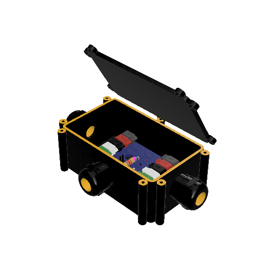
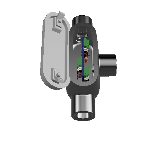
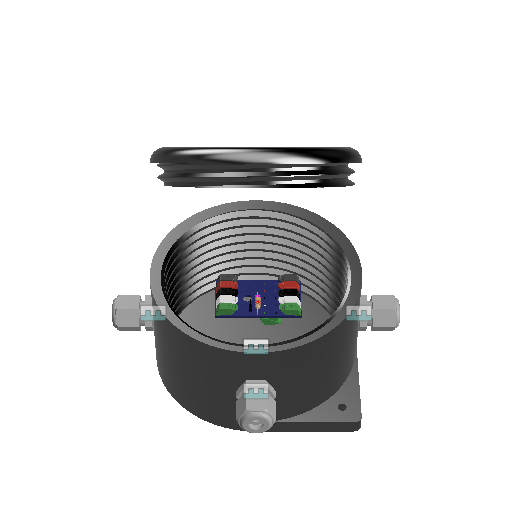
T-Port Enclosure Options
T-Port PCB
T-Port PCB is the connection interface for a bus line of TriVibe sensors.
These electrical connections allow TriVibe sensors to drop off the communication bus toward the machine.
The final T-Port in a bus (furthest from the Modbus Master, PLC, or Gateway) should have the jumper installed to enable the 12ohm resistor. Enabling this resistor is required by the RS485 standard to ensure proper communication.


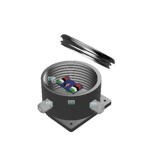
T-Port Enclosures
There are different forms of enclosures to protect the electrical connection, which runs through the T-Port PCBs, from harsh external environments.
M-687
Suitable for food and beverage applications and those not needed hazardous area ruggedness.
T-27
Suitable for hazardous environments.

 \
\UB-40
Suitable for mining and other harsh environments.
Conduit Recommendations
Option 1 (minimal cost):
The TriVibe black sensor cable is made for tough outdoor environments and is suitable for Class 1 Div. 2 areas.
You may add a ¾ NPT cable grip such as CD21NR-BXA at the T junction and use the senor as is for outdoor locations.
(1) Sealcon CD21NR-BXA (or similar) (Attaches to T PORT)
https://www.sealconusa.com/products/liquid-tight-strain-relief-fittings/nylon/bxa/npt/cd21nr-bxa/
Option 2 (higher protection):
(1 per sensor end attach to sensor) Galvanized Steel Pipe Coupling: 1/2″ Fitting
MSC# 36995116 Mfr# 420S04 (or similar)
(1 per sensor attached to the T-PORT) Reducing Bushing: Steel, Zinc Plated, 1/2 in_3/4 in Trade Size, 3/4 in to 1/2 in Reduction Size
Item 52AW35 (Granger) Mfr. Model 1142 (or similar)
(2 per sensor) Thomas & Betts 1/2" Insulated Straight Liquid Tight Connector
Brand: T&B SKU: 5332-TB (or similar)
(10 ft. per sensor) 1/2" Liquid Tight Type B Conduit ,PVC Gray (100' Coil)
Brand: T&B SKU: LTC050GY (or similar)
(alternate 10 ft. per sensor) 1/2" Liquid Tight Flexible Metallic Conduit, LFMC General Purpose UL, Gray (100' Coil)
Brand: T&B SKU: LTGUS02G-C (or similar)
Mounting Locations and Methods
Installation Tools
Required Tools
-
-
-
-
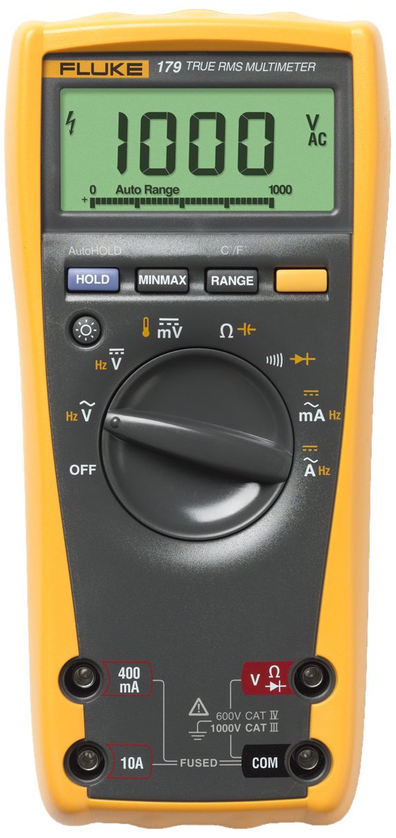
- Multimeter (Fluke 179 True RMS Multimeter Recommended)

- Wire/Cable Strippers (16-26 AWG Stranded Recommended)

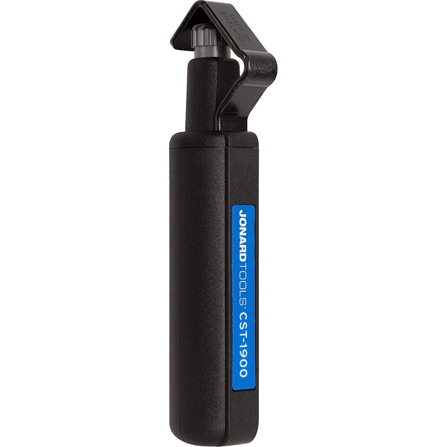
- Cable Jacket Remover (Jonard Recommended)

- Flush Cutter or Lineman's/Cutting Pliers

- Blade/Boxcutter/Scalpel

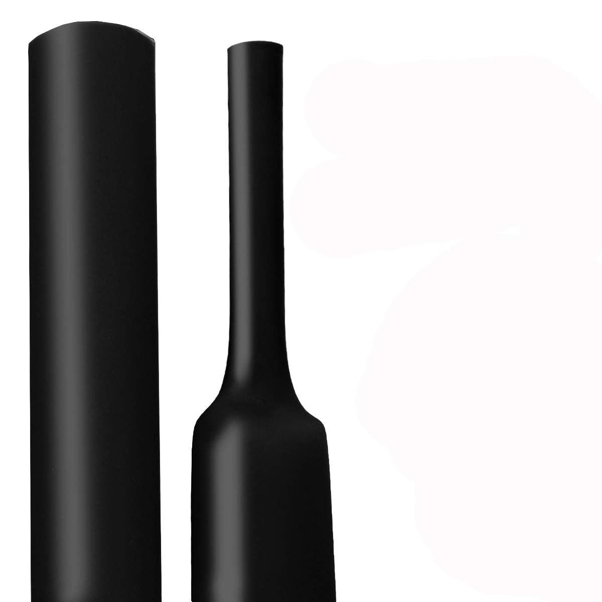
- Adhesive Lined, 1/2" Heatshrink Tubing, 3-1 Shrink Ratio

- Heat gun / Heat source

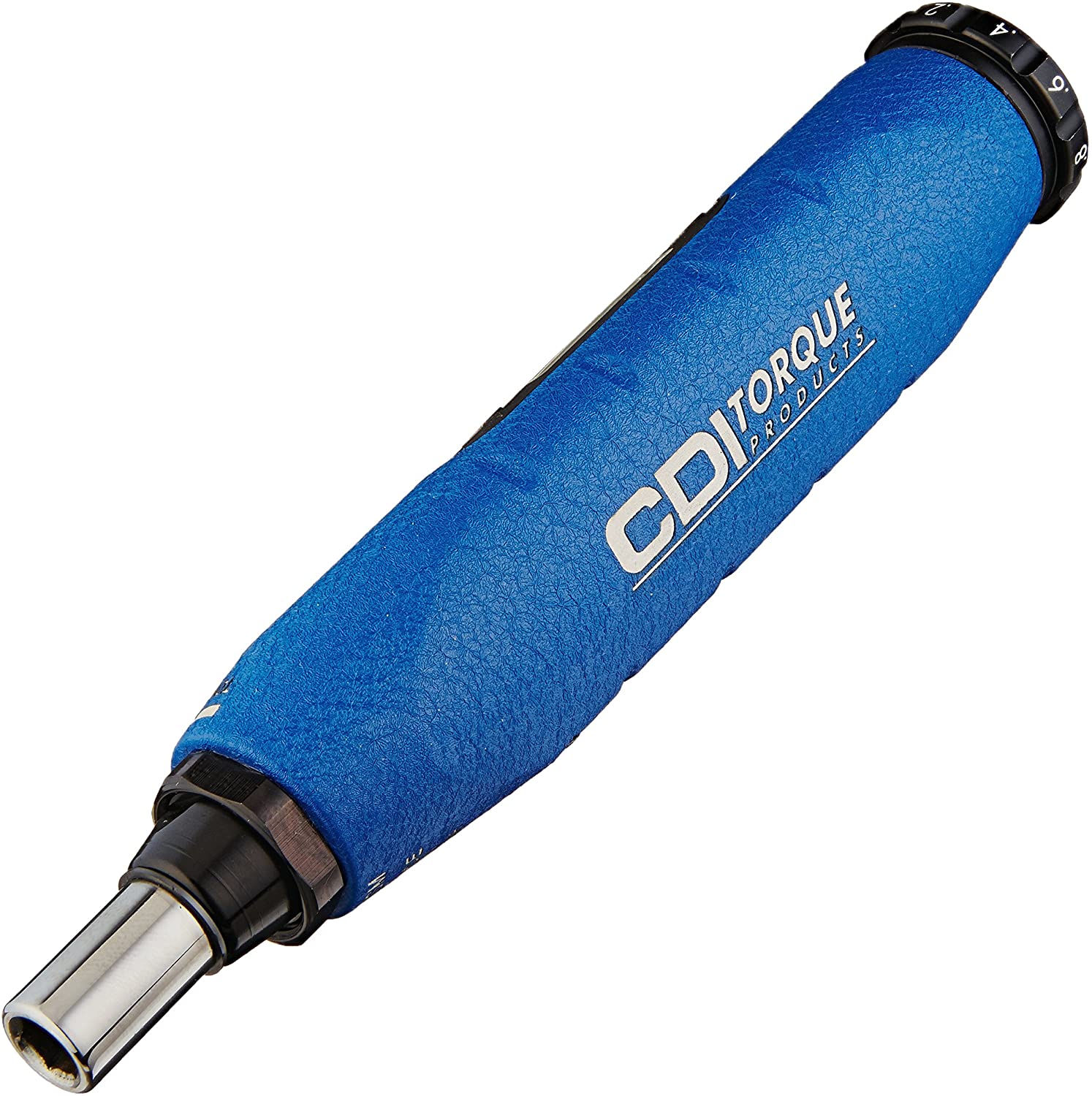
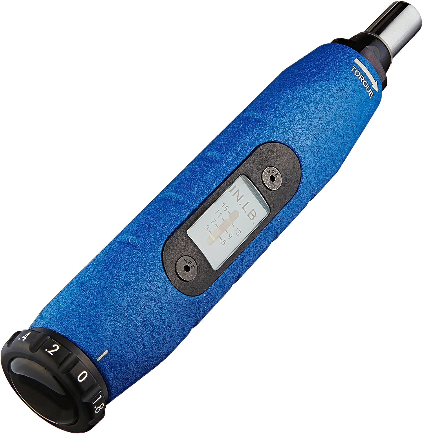
- Metric Allen Torque Wrench | 3/16" Torque-Adjustable Hex Key


- Degreasing Kit + Shop Towels


- Locktite Blue 242 Threadlocker

- Multimeter (Fluke 179 True RMS Multimeter Recommended)
-
-
-


Tools By Mounting Method
Metric Captive Bolt | Standard Captive Bolt
-
-
-
-
- Metric Bottoming Tap M6x1 | Standard Bottoming 1/4"-28 UNF Tap


- 5.0mm (13/64") Drill Bit | #3 drill bit (7/32”)
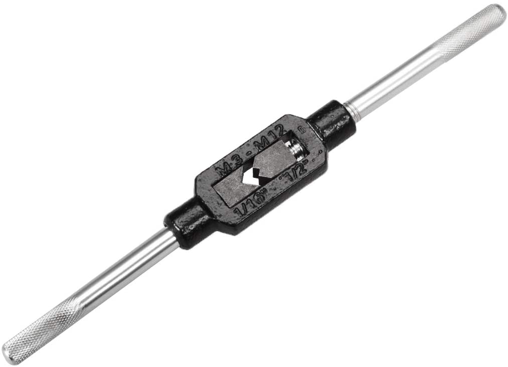
- Tap Handle

- Power Drill (We Recommend Wired and 1/2")
Note that the amp and torque requirements to cut into the case of a machine differs by case material. Select accordingly.

- Metric Bottoming Tap M6x1 | Standard Bottoming 1/4"-28 UNF Tap
-
-
-


Mounting Pad | Frenolic Block (High Heat) | Motor Fin Mount
-
-
-
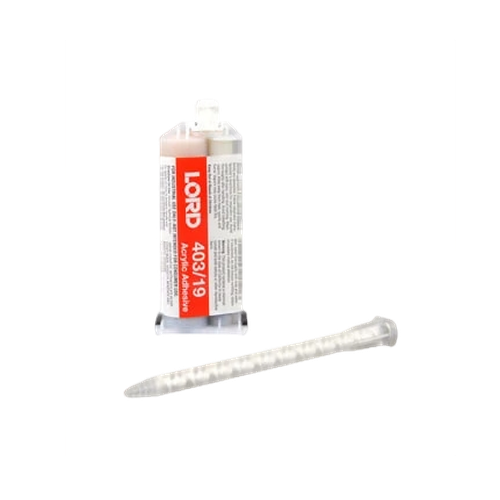
- Epoxy Cartridge (50ml LORD® 403/19 Modified Acrylic Adhesive Recommended)
Note that each 50ml cartridges contain enough epoxy to mount:
~3 Mounting Pads
~2 Frenolic Blocks
~2 Motor Fin Mounts
- Epoxy 4-1 Ratio Plunger (Compatible with Recommended Gun + Cartridge)

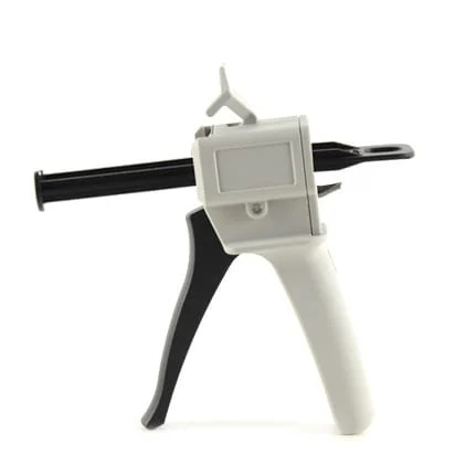
- Epoxy Gun

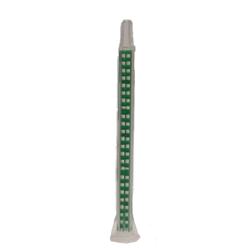
- Extra Mixer Nozzles
Note that the extra nozzles are optional but the epoxy will set within 15 minutes of sitting. If you plan to take more than 5 minutes to use the whole cartridge, you should plan on replacing the nozzle.

- Epoxy Cartridge (50ml LORD® 403/19 Modified Acrylic Adhesive Recommended)
-
-

Magnetic Mounting Pad
-
-
-
- No Additional Tools Required. Can be installed using just the required tools.
Use caution when placing the magnet on the machine. Read the mounting specific instructions before installing to avoid hurting yourself or damaging your sensors.
- No Additional Tools Required. Can be installed using just the required tools.
-
-
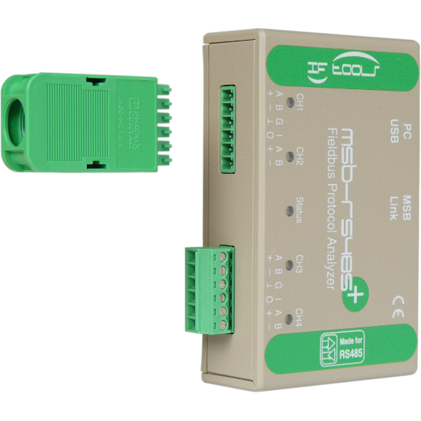
Bus Communication Verification Tools
Note that this section is specific to customers who want to use a more robust, but also more labor intensive, method to verify their RS485 Electrical Characteristics and Modbus Communications.
Imperial/US Drill + Tap (Best Method for Frequency Response)
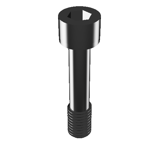
Captive Mounting Bolt 1/4"-28
Tools Required
- Power Drill
- 3/16" Allen Wrench/Hex Key
- #3 drill bit (7/32”)
- UNF 1/4"-28 Steel Tap, 3-4 Flute, Right-Hand Thread
- Captive 1/4"-28 Mounting Bolt
- Loctite Threadlocker 242 (Blue/Removable)
- Torque Wrench
Procedure
- Choose mounting location. Accelerometer/Sensor Mounting Location Selection
- Verify the machine casing is thick enough to drill 0.3 inches (7.65mm).
If the casing is not thick enough, choose a different mounting method. - Use the #3 drill bit (7/32”) to drill into the machine casing 0.3 inches (7.65mm).
The hole should be perpendicular to the face of the machine. -
Make sure to drill a straight hole. Crooked holes can result in convolution of the triaxial signals.
- Use the UNF 1/4"-28 tap to cut the threads into the drilled hole.
Be sure to keep the tap perpendicular to the face of the machine while tapping to avoid a crooked thread. - After tapping completely to the bottom of the 0.3 inches (7.65mm), clean any metal shavings from the hole and clean with a Q-Tip and degreaser.
- Insert 3/16" Allen Wrench/Hex Key into the hex depression on the captive 1/4"-28 mounting bolt.
- Screw the 1/4"-28 mounting bolt into the TriVibe, starting on the LED side.
When completely inserted, the threaded tip of the mounting bolt should stick out of the backside of the TriVibe. - Add a dab of Loctite Threadlocker 242 to the exposed threads.
-
This step is important because, over time, movement can cause the mounting bolts to become loose and result in improper vibration levels.
- Insert the wet, loctite-ed threads into the newly tapped hole.
- Rotate the Allen Wrench/Hex Key clockwise to tighten until the torque on the Allen wrench is 25.0 lb-in (3.0 N-m).
-
DO NOT OVER TIGHTEN. Excess force can damage the TriVibe.
Metric Drill + Tap (Best Method for Frequency Response)
Captive Mounting Bolt M6-1

Tools Required
- Power Drill
- 5.0mm Allen Wrench/Hex Key
- 5.0mm (13/64") Drill Bit
- ANSI M6x1 Steel Tap, 3-4 Flute, Right-Hand Thread
- Captive M6-1 Mounting Bolt
- Loctite Threadlocker 242 (Blue/Removable)
- Torque Wrench
Procedure
- Choose mounting location. Accelerometer/Sensor Mounting Location Selection
- Verify the machine casing is thick enough to drill in 7.65mm (0.3 inches).
If the casing is not thick enough, choose a different mounting method. - Use the 5.0mm (13/64") drill bit to drill into the machine casing 7.65mm (0.3 inches).
The hole should be perpendicular to the face of the machine. - Use the ANSI M6-1 tap to cut the threads into the drilled hole. Be sure to keep the tap perpendicular to the face of the machine while tapping to avoid a crooked thread.
- After tapping completely to the bottom of the 7.65mm (0.3 inches), clean any metal shavings from the hole and clean with a Q-Tip and degreaser.
- Insert 5.0mm Allen Wrench/Hex Key into the hex depression on the captive M6-1 mounting bolt.
- Fasten the 1/4"-28 captive mounting bolt into the center threads of the TriVibe, starting on top of the sensors (the side with an LED).
When completely inserted, the threaded tip of the mounting bolt should stick out the bottom of the TriVibe (opposite sied of the LED. - Add a dab of Loctite Threadlocker 242 to the exposed threads.
-
This step is important because, over time, movement can cause the mounting bolts to become loose and result in improper vibration levels.
- Insert the wet, loctite-ed threads into the newly tapped hole.
- Rotate the Allen Wrench/Hex Key clockwise to tighten until the torque on the Allen wrench is 25.0 lb-in (3.0 N-m).
-
Do not over tighten because excess external pressure/force on the housing can cause damage to the internal chops and sensors of TriVibe.
Epoxy + Mounting Pad, Phenolic Block, or Motor Fin Mount
Mounting Hardware

Instructions
-
After reading about the various mounting options and selecting a location that suits your machine application.
-
To remove all debris/dust/grease and ensure a strong bond between the mounting hardware and the metal of the machine or component, use a contact cleaner solution to clean the following:
- The mounting hardware itself.
-
The selected mounting location where the mounting hardware will contact the machine or component.
-
Locations where the curing tape will contact the machine.
-
Allow time for the contact cleaner to dry completely OR wipe clear any residual cleaner using clean shop towels.
-
Depress the black plunger of the epoxy kit to force 15ml (roughly 1/3 of the 50ml cartridge) of epoxy, through the mixing nozzle.
-
Use a tongue depressor or similar clean mixing tool to vigorously and thoroughly mix the epoxy for 30 seconds in the disposable cup. From the moment the epoxy begins mixing through the nozzle to the installation of the mounting hardware there is 2 to 4 minutes of working time @ 75°F (24°C). So Step #7 should be completed by the 4th minute.
The tip of the nozzle may also be used, in lieu of a tongue depressor, to mix the epoxy in the disposable cup.
-
Apply the epoxy to the flat side of the mounting hardware.
Be careful not to get ANY epoxy on the bolt threads or in the threaded hole while handling the sensor.
- Press the mounting hardware down on the selected mounting location. There should be enough epoxy under the mounting hardware that it pools around the edges when it is pressed down.
- Use a liberal amount of curing tape to hold the mounting hardware in place while the epoxy cures. Allow a full 10 minutes for the epoxy to cure before installing the sensor and the sensor mounting bolt. For best results, verify that nothing puts additional pressure on the sensor or mounting hardware for a full 24 hours @ room temperature, or shorter periods at higher temperatures, while the epoxy is reaching its fully cured state.
To reduce the cure time, a heat gun may be used. Hold the heat gun 4-6 inches from the epoxy while employing a gentle sweeping motion around the mounting hardware base to uniformly heat the epoxy for 10-15 minutes.
- Tighten the sensor down into the tapped hole of the mounting hardware using the instructions from the imperial/us or metric mounting bolt instructions.
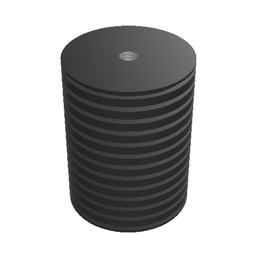
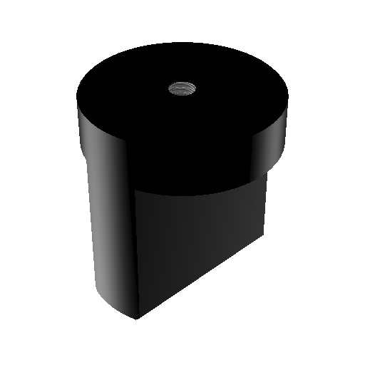
Magnetic Mounting Pad
Magnetic Mounting Pad
 The magnet mounting pad is 120 lb pull force and dimensions length 2 in, width 2 in, and height 7/8 in. Also, it has a 1/4x28” UNF mounting connection.
- Choose sensor mounting location (Sensor should be mounted perpendicular to the shaft).
- Clean the desired sensor mounting location to allow the magnet to have the best connection with the machine casing.
- Attach the TriVibe to the mounting magnet.
- Use a rolling motion to roll the magnet & TriVibe onto the machine! DO NOT just plop it on the machine as this could damage the internal accelerometers. CAUTION: keep fingers off of the silver on the magnet while attaching to machine, the force of the magnet is strong enough to seriously injure a person.
Integration
Modbus Registers Map
About these Registers:
DEVICE_ID / REMOTE_TERMINAL_UNIT (RTU) / SLAVE_ID:
Each sensor on a single multi-drop bus line must have a unique DEVICE_ID / RTU / SLAVE_ID:
By Default the DEVICE_ID / RTU / SLAVE_ID is the LAST 2 DIGITS OF THE SENSORS SERIAL NUMBER
The serial number (and therefore, the RTU number) can be found on the side of the TriVibe on the white label.
INDEXING:
Note that the listed registers below are considered 0-Indexed (the first value starts at 0)
Some Modbus masters will need to shift all the values up by one value if their master recognized the first Modbus value at 1 (known as 1-indexed).
SERIAL COMMUNICATION SETTINGS:
Baudrate: 115200
Parity: None
Handshakes: None
Data Bits: 8
Stop Bits: 1
FUNCTION CODES:
The function codes supported by TriVibe Sensor are:
03 - (0x03) READ MULTIPLE HOLDING REGISTERS
16 - (0x10) WRITE MULTIPLE HOLDING REGISTERS
--- If you want to read or write to just a single register, you can do this by setting the length/offset/number of registers to 1 ---
Endi
Endianness:
The TriVibe sensor uses the Big Endian memory allocation paradigm.
In computing, endianness is the order or sequence of bytes of a word of digital data in computer memory. Endianness is primarily expressed as big-endian (BE) or little-endian (LE). A big-endian system stores the most significant byte of a word at the smallest memory address and the least significant byte at the largest. A little-endian system, in contrast, stores the least-significant byte at the smallest address.
| Address | Name | Read / Write | Type | Description / Measurand |
| 0 | SYSTEM_INFO | Read Only | 16-Bit Unsigned Integer |
FirmwareID + Revision |
| 1 | SYSTEM_CONTROL | Read / Write | 16-Bit Unsigned Integer |
Command Values (Use with Caution):
[0] - idle |
| 2 | SYSTEM_STATUS | Read Only | 16-bit Unsigned Integer |
|
| 3 | SYSTEM_STATE1 | Read Only |
Bit Position |
MACHINE_ON_BIT 0 |
| 4 | SYSTEM_STATE2 | Read Only | Bit Position |
|
| 5 | MINUTES_ON | Read Only | 16-bit Unsigned Integer |
|
| 6 | HOURS_ON | Read Only | 16-bit Unsigned Integer |
|
| 7 | DAYS_ON | Read Only | 16-bit Unsigned Integer |
|
| 8 | SYSTEM_DEBUG1 | Read Only | 16-bit Unsigned Integer |
|
| 9 | SYSTEM_DEBUG2 | Read Only | 16-bit Unsigned Integer |
|
| 10 | Last Command of SYSTEM_CONTROL | Read Only | 16-bit Unsigned Integer |
|
| 11 | PERIPHERAL_STATE | Read Only | Bit Position | I2C_BUS_BIT 0 |
| 12 | DDR_CONTROLLER_RESTART | Read / Write | 16-bit Unsigned Integer |
|
| 13 | LAST_SYSTEM_FLAG | Read Only | 16-bit Unsigned Integer |
|
| 14 | SYSTEM_MODE | Read Only | Bit Position | ENABLE_COLLECT_BIT_FLAG 0 ENABLE_IMPACT_BIT_FLAG 1 ENABLE_DETONATION_BIT_FLAG 2 ENABLE_EXT_IMPACT_BIT_FLAG 3 |
| 15 | SYSTEM_FLAG | Read Only | 16-bit Unsigned Integer |
|
| 16 | SYSTEM_ECU | Read Only | 16-bit Unsigned Integer |
|
| 17 | SYSTEM_RTU | Read Only | 16-bit Unsigned Integer |
|
| 18 | HIGH_DATA_POINTER | Read/Write | 32-bit Unsigned Integer |
|
| 19 | LOW_DATA_POINTER | Read/Write | ||
| 20 | HIGH_UIDH | Read Only | 32-bit Unsigned Integer |
|
| 21 | LOW_UIDH | Read Only | ||
| 22 | HIGH_UIDMH | Read Only | 32-bit Unsigned Integer |
|
| 23 | LOW_UIDMH | Read Only | ||
| 24 | HIGH_UIDML | Read Only | 32-bit Unsigned Integer |
|
| 25 | LOW_UIDML | Read Only | ||
| 26 | HIGH_SERIAL_NUMBER (UIDL) | Read Only | 32-bit Unsigned Integer |
|
| 27 | LOW__SERIAL_NUMBER (UIDL) | Read Only | ||
| 28 | TEMP_SENSOR_READ_STATS | Read Only | 16-bit Unsigned Integer |
|
| 29 | TEMP_SENSOR_READ_FLAG_STATS | Read Only | 16-bit Unsigned Integer |
|
| 30 | TEMP_SENSOR_TYPE | Read Only | Bit Position |
|
| 31 | TEMPERATURE | Read Only | 16-bit Signed Integer |
Divide Value / 10 |
| 32 | DDC_AXIS | Read / Write | 16-bit Unsigned Integer |
|
| 33 | DDC_CONTROL_RAW | Write Only | 16-bit Unsigned Integer |
|
| 34 | DDC_CAPTURE_ENGINE_STATUS | Read / Write | 16-bit Unsigned Integer |
|
| 35 | DDC_CAPTURE_TIME_MS | Read / Write | 16-bit Unsigned Integer |
|
| 36 | DDC_HIGH_SAMPLES_PER_AXIS | Read / Write | 32-bit Unsighed Integer |
|
| 37 | DDC_LOW_SAMPLES_PER_AXIS | Read / Write | ||
| 38 | ADC_STATUS | Read Only | Bit Position |
|
| 39 | AXIS_1_SENSOR_1_DETONATION | Read Only | 16-bit Unsigned Integer |
|
| 40 | AXIS_2_SENSOR_1_DETONATION | Read Only | 16-bit Unsigned Integer |
|
| 41 | AXIS_3_SENSOR_1_DETONATION | Read Only | 16-bit Unsigned Integer |
|
| 42 | AXIS_1_SENSOR_2_DETONATION | Read Only | 16-bit Unsigned Integer |
|
| 43 | AXIS_2_SENSOR_2_DETONATION | Read Only | 16-bit Unsigned Integer |
|
| 44 | AXIS_2_SENSOR_2_DETONATION | Read Only | 16-bit Unsigned Integer |
|
| 45 | IMPACT_ALERT | Read Only | 16-bit Unsigned Integer |
|
| 46 | IMPACT_DANGER | Read Only | 16-bit Unsigned Integer |
|
| 47 | IMPACT_AVERAGED_ALERT | Read Only | 16-bit Unsigned Integer |
|
| 48 | IMPACT_AVERAGED_DANGER | Read Only | 16-bit Unsigned Integer |
|
| 49 | DDC_START_SAMPLE | Read / Write | 16-bit Unsigned Integer |
This register will start by holding a 0 (indicating the 0th sample is in register 50, ready to be read). After successfully reading the data clip sample in register 171, this register should read 122 (indicating the 122nd sample is in register 50, ready to be read). |
| 50-171 | DDC_SAMPLES | Read Only | 16-bit Unsigned Integers |
Block reads of registers 49 - 171 repeatedly until your SAMPLES_PER_AXIS * 3 are collected to your Modbus Master is the recommended approach for collecting dynamic data clips. |
| 171 | DDC_SAMPLES_AUTO_INCREMENT | Read Only | 16-bit Unsigned Integer |
Each time register 171 is successfully read by a Modbus Master. Register 49 is updated to reflect the index of the sample in register 50 and the next set of DDC Samples is loaded into registers 50 - 171. |
| 172 | HIGH_AXIS_1_ACCELERATION | Read Only | 32-bit Floating Point |
g_RMS |
| 173 | LOW_AXIS_1_ACCELERATION | Read Only | ||
| 174 | HIGH_AXIS_2_ACCELERATION | Read Only | 32-bit Floating Point |
g_RMS |
| 175 | LOW_AXIS_2_ACCELERATION | Read Only | ||
| 176 | HIGH_AXIS_3_ACCELERATION | Read Only | 32-bit Floating Point |
g_RMS |
| 177 | LOW_AXIS_3_ACCELERATION | Read Only | ||
| 178 | HIGH_AXIS_1_VELOCITY | Read Only | 32-bit Floating Point |
in/sec_RMS |
| 179 | LOW_AXIS_1_VELOCITY | Read Only | ||
| 180 | HIGH_AXIS_2_VELOCITY | Read Only | 32-bit Floating Point |
in/sec_RMS |
| 181 | LOW_AXIS_2_VELOCITY | Read Only | ||
| 182 | HIGH_AXIS_3_VELOCITY | Read Only | 32-bit Floating Point |
in/sec_RMS |
| 183 | LOW_AXIS_3_VELOCITY | Read Only | ||
| 184 | HIGH_AXIS_1_DISPLACEMENT | Read Only | 32-bit Floating Point |
mils |
| 185 | LOW_AXIS_1_DISPLACEMENT | Read Only | ||
| 186 | HIGH_AXIS_2_DISPLACEMENT | Read Only | 32-bit Floating Point |
mils |
| 187 | LOW_AXIS_2_DISPLACEMENT | Read Only | ||
| 188 | HIGH_AXIS_3_DISPLACEMENT | Read Only | 32-bit Floating Point |
mils |
| 189 | LOW_AXIS_3_DISPLACEMENT | Read Only | ||
| 190 | INTERNAL_ACCELEROMETER_1_HIGH_AXIS_1_ACCELERATION | Read Only | 32-bit Floating Point |
g_RMS |
| 191 | INTERNAL_ACCELEROMETER_1_LOW_AXIS_1_ACCELERATION | Read Only | ||
| 192 | INTERNAL_ACCELEROMETER_1_HIGH_AXIS_2_ACCELERATION | Read Only | 32-bit Floating Point |
g_RMS |
| 193 | INTERNAL_ACCELEROMETER_1_LOW_AXIS_2_ACCELERATION | Read Only | ||
| 194 | INTERNAL_ACCELEROMETER_1_HIGH_AXIS_3_ACCELERATION | Read Only | 32-bit Floating Point |
g_RMS |
| 195 | INTERNAL_ACCELEROMETER_1_LOW_AXIS_3_ACCELERATION | Read Only | ||
| 196 | INTERNAL_ACCELEROMETER_1_HIGH_AXIS_1_VELOCITY | Read Only | 32-bit Floating Point |
in/sec_RMS |
| 197 | INTERNAL_ACCELEROMETER_1_LOW_AXIS_1_VELOCITY | Read Only | ||
| 198 | INTERNAL_ACCELEROMETER_1_HIGH_AXIS_2_VELOCITY | Read Only | 32-bit Floating Point |
in/sec_RMS |
| 199 | INTERNAL_ACCELEROMETER_1_LOW_AXIS_2_VELOCITY | Read Only | ||
| 200 | INTERNAL_ACCELEROMETER_1_HIGH_AXIS_3_VELOCITY | Read Only | 32-bit Floating Point |
in/sec_RMS |
| 201 | INTERNAL_ACCELEROMETER_1_LOW_AXIS_3_VELOCITY | Read Only | ||
| 202 | INTERNAL_ACCELEROMETER_1_HIGH_AXIS_1_DISPLACEMENT | Read Only | 32-bit Floating Point |
mils |
| 203 | INTERNAL_ACCELEROMETER_1_LOW_AXIS_1_DISPLACEMENT | Read Only | ||
| 204 | INTERNAL_ACCELEROMETER_1_HIGH_AXIS_2_DISPLACEMENT | Read Only | 32-bit Floating Point |
mils |
| 205 | INTERNAL_ACCELEROMETER_1_LOW_AXIS_2_DISPLACEMENT | Read Only | ||
| 206 | INTERNAL_ACCELEROMETER_1_HIGH_AXIS_3_DISPLACEMENT | Read Only | 32-bit Floating Point |
mils |
| 207 | INTERNAL_ACCELEROMETER_1_LOW_AXIS_3_DISPLACEMENT | Read Only | ||
| 208 | INTERNAL_ACCELEROMETER_2_HIGH_AXIS_1_ACCELERATION | Read Only | 32-bit Floating Point |
g_RMS |
| 209 | INTERNAL_ACCELEROMETER_2_LOW_AXIS_1_ACCELERATION | Read Only | ||
| 210 | INTERNAL_ACCELEROMETER_2_HIGH_AXIS_2_ACCELERATION | Read Only | 32-bit Floating Point |
g_RMS |
| 211 | INTERNAL_ACCELEROMETER_2_LOW_AXIS_2_ACCELERATION | Read Only | ||
| 212 | INTERNAL_ACCELEROMETER_2_HIGH_AXIS_3_ACCELERATION | Read Only | 32-bit Floating Point |
g_RMS |
| 213 | INTERNAL_ACCELEROMETER_2_LOW_AXIS_3_ACCELERATION | Read Only | ||
| 214 | INTERNAL_ACCELEROMETER_2_HIGH_AXIS_1_VELOCITY | Read Only | 32-bit Floating Point |
in/sec_RMS |
| 215 | INTERNAL_ACCELEROMETER_2_LOW_AXIS_1_VELOCITY | Read Only | ||
| 216 | INTERNAL_ACCELEROMETER_2_HIGH_AXIS_2_VELOCITY | Read Only | 32-bit Floating Point |
in/sec_RMS |
| 217 | INTERNAL_ACCELEROMETER_2_LOW_AXIS_2_VELOCITY | Read Only | ||
| 218 | INTERNAL_ACCELEROMETER_2_HIGH_AXIS_3_VELOCITY | Read Only | 32-bit Floating Point |
in/sec_RMS |
| 219 | INTERNAL_ACCELEROMETER_2_LOW_AXIS_3_VELOCITY | Read Only | ||
| 220 | INTERNAL_ACCELEROMETER_2_HIGH_AXIS_1_DISPLACEMENT | Read Only | 32-bit Floating Point |
mils |
| 221 | INTERNAL_ACCELEROMETER_2_LOW_AXIS_1_DISPLACEMENT | Read Only | ||
| 222 | INTERNAL_ACCELEROMETER_2_HIGH_AXIS_2_DISPLACEMENT | Read Only | 32-bit Floating Point |
mils |
| 223 | INTERNAL_ACCELEROMETER_2_LOW_AXIS_2_DISPLACEMENT | Read Only | ||
| 224 | INTERNAL_ACCELEROMETER_2_HIGH_AXIS_3_DISPLACEMENT | Read Only | 32-bit Floating Point |
mils |
| 225 | INTERNAL_ACCELEROMETER_2_LOW_AXIS_3_DISPLACEMENT | Read Only | ||
| 226 | ALARM_1_STATE | Read Only | 16-bit Unsigned Integer |
|
| 227 | ALARM_2_STATE | Read Only | 16-bit Unsigned Integer |
|
| 228 | ALARM_3_STATE | Read Only | 16-bit Unsigned Integer |
|
| 229 | ALARM_4_STATE | Read Only | 16-bit Unsigned Integer |
|
| 230 | HIGH_ALARM_1_HIGHEST_VALUE | Read Only | 32-bit Floating Point |
|
| 231 | LOW_ALARM_1_HIGHEST_VALUE | Read Only | ||
| 232 | HIGH_ALARM_2_HIGHEST_VALUE | Read Only | 32-bit Floating Point |
|
| 233 | LOW_ALARM_2_HIGHEST_VALUE | Read Only | ||
| 234 | HIGH_ALARM_3_HIGHEST_VALUE | Read Only | 32-bit Floating Point |
|
| 235 | LOW_ALARM_3_HIGHEST_VALUE | Read Only | ||
| 236 | HIGH_ALARM_4_HIGHEST_VALUE | Read Only | 32-bit Floating Point |
|
| 237 | LOW_ALARM_4_HIGHEST_VALUE | Read Only | ||
| 238 | ALARM_CONTROL | Read / Write | Bit Position |
|
| 239 | HIGH_ALARM_1_NORMAL | Read / Write | 32-bit Floating Point |
|
| 240 | LOW_ALARM_1_NORMAL | Read / Write | ||
| 241 | HIGH_ALARM_2_NORMAL | Read / Write | 32-bit Floating Point |
|
| 242 | LOW_ALARM_2_NORMAL | Read / Write | ||
| 243 | HIGH_ALARM_3_NORMAL | Read / Write | 32-bit Floating Point |
|
| 244 | LOW_ALARM_3_NORMAL | Read / Write | ||
| 245 | HIGH_ALARM_4_NORMAL | Read / Write | 32-bit Floating Point |
|
| 246 | LOW_ALARM_4_NORMAL | Read / Write | ||
| 247 | HIGH_ALARM_1_LO | Read / Write | 32-bit Floating Point |
|
| 248 | LOW_ALARM_1_LO | Read / Write | ||
| 249 | HIGH_ALARM_2_LO | Read / Write | 32-bit Floating Point |
|
| 250 | LOW_ALARM_2_LO | Read / Write | ||
| 251 | HIGH_ALARM_3_LO | Read / Write | 32-bit Floating Point |
|
| 252 | LOW_ALARM_3_LO | Read / Write | ||
| 253 | HIGH_ALARM_4_LO | Read / Write | 32-bit Floating Point |
|
| 254 | LOW_ALARM_4_LO | Read / Write | ||
| 255 | HIGH_ALARM_1_HI | Read / Write | 32-bit Floating Point |
|
| 256 | LOW_ALARM_1_HI | Read / Write | ||
| 257 | HIGH_ALARM_2_HI | Read / Write | 32-bit Floating Point |
|
| 258 | LOW_ALARM_2_HI | Read / Write | ||
| 259 | HIGH_ALARM_3_HI | Read / Write | 32-bit Floating Point |
|
| 260 | LOW_ALARM_3_HI | Read / Write | ||
| 261 | HIGH_ALARM_4_HI | Read / Write | 32-bit Floating Point |
|
| 262 | LOW_ALARM_4_HI | Read / Write | ||
| 263 | HIGH_ALARM_1_HIHI | Read / Write | 32-bit Floating Point |
|
| 264 | LOW_ALARM_1_HIHI | Read / Write | ||
| 265 | HIGH_ALARM_2_HIHI | Read / Write | 32-bit Floating Point |
|
| 266 | LOW_ALARM_2_HIHI | Read / Write | ||
| 267 | HIGH_ALARM_3_HIHI | Read / Write | 32-bit Floating Point |
|
| 268 | LOW_ALARM_3_HIHI | Read / Write | ||
| 269 | HIGH_ALARM_4_HIHI | Read / Write | 32-bit Floating Point |
|
| 270 | LOW_ALARM_4_HIHI | Read / Write | ||
| 272 | ALARM_MULTIPLIER | Read / Write | ||
| 273-276 | RESERVED | - | - | - |
| 277 | MODBUS_RELEASE | Read Only | 16-bit Unsigned Integer |
|
| 278 | AXIS_1_SENSOR_1_EXT_IMPACT_ALERT | Read Only | 16-bit Unsigned Integer |
|
| 279 | AXIS_2_SENSOR_1_EXT_IMPACT_ALERT | Read Only | 16-bit Unsigned Integer |
|
| 280 | AXIS_3_SENSOR_1_EXT_IMPACT_ALERT | Read Only | 16-bit Unsigned Integer |
|
| 281 | AXIS_1_SENSOR_2_EXT_IMPACT_ALERT | Read Only | 16-bit Unsigned Integer |
|
| 282 | AXIS_2_SENSOR_2_EXT_IMPACT_ALERT | Read Only | 16-bit Unsigned Integer |
|
| 283 | AXIS_3_SENSOR_2_EXT_IMPACT_ALERT | Read Only | 16-bit Unsigned Integer |
|
| 284 | AXIS_1_SENSOR_1_EXT_IMPACT_DANGER | Read Only | 16-bit Unsigned Integer |
|
| 285 | AXIS_2_SENSOR_1_EXT_IMPACT_DANGER | Read Only | 16-bit Unsigned Integer |
|
| 286 | AXIS_3_SENSOR_1_EXT_IMPACT_DANGER | Read Only | 16-bit Unsigned Integer |
|
| 287 | AXIS_1_SENSOR_2_EXT_IMPACT_DANGER | Read Only | 16-bit Unsigned Integer |
|
| 288 | AXIS_2_SENSOR_2_EXT_IMPACT_DANGER | Read Only | 16-bit Unsigned Integer |
|
| 289 | AXIS_3_SENSOR_2_EXT_IMPACT_DANGER | Read Only | 16-bit Unsigned Integer |
|
| 290 | AXIS_1_SENSOR_1_EXT_IMPACT_SEVERITY | Read Only | 16-bit Unsigned Integer |
Returned Value = GPK*10 |
| 291 | AXIS_2_SENSOR_1_EXT_IMPACT_SEVERITY | Read Only | 16-bit Unsigned Integer |
Returned Value = GPK*10 |
| 292 | AXIS_3_SENSOR_1_EXT_IMPACT_SEVERITY | Read Only | 16-bit Unsigned Integer |
Returned Value = GPK*10 |
| 293 | AXIS_1_SENSOR_2_EXT_IMPACT_SEVERITY | Read Only | 16-bit Unsigned Integer |
Returned Value = GPK*10 |
| 294 | AXIS_2_SENSOR_2_EXT_IMPACT_SEVERITY | Read Only | 16-bit Unsigned Integer |
Returned Value = GPK*10 |
| 295 | AXIS_3_SENSOR_2_EXT_IMPACT_SEVERITY | Read Only | 16-bit Unsigned Integer |
Returned Value = GPK*10 |
| 296 | ALGORITHM_TIME | Read / Write | 16-bit Unsigned Integer |
Milliseconds |
| 297 | INVALID_DATA_COUNTER | Read Only | 16-bit Unsigned Integer |
|
| 298 | SECURITY_REGSTER | Read Only | 16-bit Unsigned Integer |
|
| 299 | HIGH_A1S1_SENSITIVITY_REGISTER | Read / Write | 32-bit Floating Point |
|
| 300 | LOW_A1S1_SENSITIVITY_REGISTER | Read / Write | ||
| 301 | HIGH_A2S1_SENSITIVITY_REGISTER | Read / Write | 32-bit Floating Point |
|
| 302 | LOW_A2S1_SENSITIVITY_REGISTER | Read / Write | ||
| 303 | HIGH_A3S1_SENSITIVITY_REGISTER | Read / Write | 32-bit Floating Point |
|
| 304 | LOW_A3S1_SENSITIVITY_REGISTER | Read / Write | ||
| 305 | HIGH_A1S2_SENSITIVITY_REGISTER | Read / Write | 32-bit Floating Point |
|
| 306 | LOW_A1S2_SENSITIVITY_REGISTER | Read / Write | ||
| 307 | HIGH_A2S2_SENSITIVITY_REGISTER | Read / Write | 32-bit Floating Point |
|
| 308 | LOW_A2S2_SENSITIVITY_REGISTER | Read / Write | ||
| 309 | HIGH_A3S2_SENSITIVITY_REGISTER | Read / Write | 32-bit Floating Point |
|
| 310 | LOW_A3S2_SENSITIVITY_REGISTER | Read / Write | ||
| 311 | ALARM_TRIP_DELAY | Read / Write | 16-bit Unsigned Integer |
This delay is applied to all 4 Alarm Channels |
| 312 | ALARM1_AXIS | Read / Write | 16-bit Unsigned Integer |
|
| 313 | ALARM1_TYPE | Read / Write | 16-bit Unsigned Integer |
|
| 314 | ALARM1_LO_LEVEL_HIGH | Read / Write | 32-bit Floating Point |
|
| 315 | ALARM1_LO_LEVEL_LOW | Read / Write | ||
| 316 | ALARM1_HI_LEVEL_HIGH | Read / Write | 32-bit Floating Point |
|
| 317 | ALARM1_HI_LEVEL_LOW | Read / Write | ||
| 318 | ALARM1_HIHI_LEVEL_HIGH | Read / Write | 32-bit Floating Point |
|
| 319 | ALARM1_HIHI_LEVEL_LOW | Read / Write | ||
| 320 | ALARM1_HYSTERESIS_HIGH | Read / Write | 32-bit Floating Point |
|
| 321 | ALARM1_HYSTERESIS_LOW | Read / Write | ||
| 322 | ALARM2_AXIS | Read / Write | 16-bit Unsigned Integer |
|
| 323 | ALARM2_TYPE | Read / Write | 16-bit Unsigned Integer |
|
| 324 | ALARM2_LO_LEVEL_HIGH | Read / Write | 32-bit Floating Point |
|
| 325 | ALARM2_LO_LEVEL_LOW | Read / Write | ||
| 326 | ALARM2_HI_LEVEL_HIGH | Read / Write | 32-bit Floating Point |
|
| 327 | ALARM2_HI_LEVEL_LOW | Read / Write | ||
| 328 | ALARM2_HIHI_LEVEL_HIGH | Read / Write | 32-bit Floating Point |
|
| 329 | ALARM2_HIHI_LEVEL_LOW | Read / Write | ||
| 330 | ALARM2_HYSTERESIS_HIGH | Read / Write | 32-bit Floating Point |
|
| 331 | ALARM2_HYSTERESIS_LOW | Read / Write | ||
| 332 | ALARM3_AXIS | Read / Write | 16-bit Unsigned Integer |
|
| 333 | ALARM3_TYPE | Read / Write | 16-bit Unsigned Integer |
|
| 334 | ALARM3_LO_LEVEL_HIGH | Read / Write | 32-bit Floating Point |
|
| 335 | ALARM3_LO_LEVEL_LOW | Read / Write | ||
| 336 | ALARM3_HI_LEVEL_HIGH | Read / Write | 32-bit Floating Point |
|
| 337 | ALARM3_HI_LEVEL_LOW | Read / Write | ||
| 338 | ALARM3_HIHI_LEVEL_HIGH | Read / Write | 32-bit Floating Point |
|
| 339 | ALARM3_HIHI_LEVEL_LOW | Read / Write | ||
| 340 | ALARM3_HYSTERESIS_HIGH | Read / Write | 32-bit Floating Point |
|
| 341 | ALARM3_HYSTERESIS_LOW | Read / Write | ||
| 342 | ALARM4_AXIS | Read / Write | 16-bit Unsigned Integer |
|
| 343 | ALARM4_TYPE | Read / Write | 16-bit Unsigned Integer |
|
| 344 | ALARM4_LO_LEVEL_HIGH | Read / Write | 32-bit Floating Point |
|
| 345 | ALARM4_LO_LEVEL_LOW | Read / Write | ||
| 346 | ALARM4_HI_LEVEL_HIGH | Read / Write | 32-bit Floating Point |
|
| 347 | ALARM4_HI_LEVEL_LOW | Read / Write | ||
| 348 | ALARM4_HIHI_LEVEL_HIGH | Read / Write | 32-bit Floating Point |
|
| 349 | ALARM4_HIHI_LEVEL_LOW | Read / Write | ||
| 350 | ALARM4_HYSTERESIS_HIGH | Read / Write | 32-bit Floating Point |
|
| 351 | ALARM4_HYSTERESIS_LOW | Read / Write | ||
| 352 | A1S1_ZERO | Read / Write | 16-bit Unsigned Integer |
|
| 353 | A2S1_ZERO | Read / Write | 16-bit Unsigned Integer |
|
| 354 | A3S1_ZERO | Read / Write | 16-bit Unsigned Integer |
|
| 355 | A1S2_ZERO | Read / Write | 16-bit Unsigned Integer |
|
| 356 | A2S2_ZERO | Read / Write | 16-bit Unsigned Integer |
|
| 357 | A3S2_ZERO | Read / Write | 16-bit Unsigned Integer |
|
| 358 | BUFFER_1_SECONDS | Read / Write | 16-bit Unsigned Integer |
|
| 359 | BUFFER_1_FFT_POINTS | Read / Write | 16-bit Unsigned Integer |
|
| 360 | BUFFER_1_FILTER_TYPE | Read / Write | 16-bit Unsigned Integer |
|
| 361 | BUFFER_1_FILTER_MODE | Read / Write | Bit Position |
|
| 362 | BUFFER_2_SECONDS | Read / Write | 16-bit Unsigned Integer |
|
| 363 | BUFFER_2_FFT_POINTS | Read / Write | 16-bit Unsigned Integer |
|
| 364 | BUFFER_2_FILTER_TYPE | Read / Write | 16-bit Unsigned Integer |
|
| 365 | BUFFER_2_FILTER_MODE | Read / Write | Bit Position |
|
| 366 | BOARD_TYPE | Read / Write | 16-bit Unsigned Integer |
|
| 367 | SENSOR_RTU | Read / Write | 16-bit Unsigned Integer |
|
| 368 | IMPACT_ALERT_THRESHOLD | |||
| 369 | ||||
| 370 | IMPACT_DANGER_THRESHOLD | |||
| 371 | ||||
| 372 | MACHINE_SPEED_CONFIG | |||
| 373 | CONFIG_SYSTEM_MODE | |||
| 374 | RESET_COUNTER_CONFIG | |||
| 375 | LOW_PASS_FREQUENCY |
CONFIG 1. Unlock: write [45555] to SYSTEM_CONTROL
SYSTEM_CONTROL |
16-bit Unsigned Integer |
0.1 Hz per bit
Example: If wish for a lowpass filter of 2500Hz, Write value [25000]
This value must be higher than your setting for HIGH_PASS_FREQUENCY. |
| 376 | HIGH_PASS_FREQUENCY |
CONFIG 1. Unlock: write [45555] to SYSTEM_CONTROL
SYSTEM_CONTROL |
16-bit Unsigned Integer |
0.1 Hz per bit
Example: If wish for a highpass filter of 25Hz, Write value [250]
This value must be lower than your setting for LOW_PASS_FREQUENCY. |
| 377 | LATCH_TYPE | */ #define MODBUS_LATCH_TYPE_REGISTER (40378-40001) #define MODBUS_LATCH_TYPE_IDLE 0 /* Catch the "highest value clip" commands */ #define MODBUS_LATCH_TYPE_VELOCITY 10 #define MODBUS_LATCH_TYPE_A1_VELOCITY 11 #define MODBUS_LATCH_TYPE_A2_VELOCITY 12 #define MODBUS_LATCH_TYPE_A3_VELOCITY 13 // #define MODBUS_LATCH_TYPE_ACCELERATION 20 #define MODBUS_LATCH_TYPE_A1_ACCELERATION 21 #define MODBUS_LATCH_TYPE_A2_ACCELERATION 22 #define MODBUS_LATCH_TYPE_A3_ACCELERATION 23 // #define MODBUS_LATCH_TYPE_TEMPERATURE 30 /* Catch the "first value clip" commands */ #define MODBUS_LATCH_TYPE_FIRST_OFFSET 0x100 #define MODBUS_LATCH_TYPE_FIRST_VELOCITY (MODBUS_LATCH_TYPE_VELOCITY+MODBUS_LATCH_TYPE_FIRST_OFFSET) #define MODBUS_LATCH_TYPE_A1_FIRST_VELOCITY (MODBUS_LATCH_TYPE_A1_VELOCITY+MODBUS_LATCH_TYPE_FIRST_OFFSET) #define MODBUS_LATCH_TYPE_A2_FIRST_VELOCITY (MODBUS_LATCH_TYPE_A2_VELOCITY+MODBUS_LATCH_TYPE_FIRST_OFFSET) #define MODBUS_LATCH_TYPE_A3_FIRST_VELOCITY (MODBUS_LATCH_TYPE_A3_VELOCITY+MODBUS_LATCH_TYPE_FIRST_OFFSET) // #define MODBUS_LATCH_TYPE_FIRST_ACCELERATION (MODBUS_LATCH_TYPE_ACCELERATION+MODBUS_LATCH_TYPE_FIRST_OFFSET) #define MODBUS_LATCH_TYPE_A1_FIRST_ACCELERATION (MODBUS_LATCH_TYPE_A1_ACCELERATION+MODBUS_LATCH_TYPE_FIRST_OFFSET) #define MODBUS_LATCH_TYPE_A2_FIRST_ACCELERATION (MODBUS_LATCH_TYPE_A2_ACCELERATION+MODBUS_LATCH_TYPE_FIRST_OFFSET) #define MODBUS_LATCH_TYPE_A3_FIRST_ACCELERATION (MODBUS_LATCH_TYPE_A3_ACCELERATION+MODBUS_LATCH_TYPE_FIRST_OFFSET) // #define MODBUS_LATCH_TYPE_FIRST_TEMPERATURE (MODBUS_LATCH_TYPE_TEMPERATURE+MODBUS_LATCH_TYPE_FIRST_OFFSET) /* |
||
| 378 | LATCH LEVEL HIGH | |||
| 379 | LATCH LEVEL LOW |
|||
| 380 | SENSOR CONTROL | Bit Position |
|
|
| 381 | ALGORITHM_REGISTER | Bit Position |
|
|
| 382 | CONFIG_ALARM_MULTIPLIER | |||
| 383 | OFF_THRESHOLD_HIGH | |||
| 384 | OFF_THRESHOLD_LOW |
|||
| 385 | ON_THRESHOLD_HIGH | |||
| 386 | ON_THRESHOLD_LOW |
|||
| 387 | OFF_TIME | |||
| 388 | ON_TIME |
|||
| 389 | RESERVED NON-VOLATILE CONFIG | |||
| 390 | RESET COUNTER | |||
| 391 | RESET_SOURCE |
|
||
| 392 | RESET_STATUS |
|
||
| 393 | LATCH_COMMAND |
|
||
| 394 | LATCH_STATUS |
|
LED Status
Note for users: If you see any states besides Solid GREEN or Blinking GREEN, please contact Machine Saver technical support for troubleshooting assistance.
|
LED State |
Description |
|
Solid GREEN |
All subsystems are good, no vibration alarms |
|
Blinking GREEN |
Vibration Alarms |
|
Solid RED |
Internal Hardware Error |
|
Alternating 2RED, 2GREEN |
Bootloader Mode |
|
Alternating 1RED, 1GREEN |
Bootloader Mode (Older Version ) |
|
Alternating 3RED, 1GREEN |
Calibration Issue |
Jupyter Notebook Setup
About Jupyter Notebooks:
https://jupyter-notebook-beginner-guide.readthedocs.io/en/latest/
Installing and Opening Jupyter Notebook Instructions:
- Installing Anaconda (Python 3.7 Version) to your computer - https://www.anaconda.com/distribution/
- Make sure that during installation you select the option:
Add Anaconda to my PATH environment variable - After installation is complete open up an Anaconda Prompt
- In the Anaconda Prompt type the command:
conda install -c conda-forge minimalmodbus
If HTTPS error occurs…
Connect to the internet and re-run the previous command. - When prompted to Proceed ([y]/n)?
Respond: yes or yPress the ENTER key to submit
This will install the necessary Modbus master library that is required by the attached notebook. - In the Anaconda Prompt type the command:
conda install plotly - When prompted to Proceed ([y]/n)?
Respond: yes or y
Press the ENTER key to submit
This will install the necessary plotting library that is required by the attached notebook. - Open Anaconda Navigator
- Once Navigator is open, launch Jupyter Notebooks
- Upon launching Jupyter Notebooks, a web browser should open.
-
Using the interface within the web browser, navigate to the directory/folder where you extracted and saved the notebook file (often in Downloads) and click on the notebook file:
https://gitlab.com/machine_saver_public/notebooks/-/blob/master/modbus_master_examples.ipynb
Refactored Analysis Data Capture Code Example
from datetime import datetime
import json, math, minimalmodbus
import numpy as np
#import os
#import plotly.graph_objects as go
from scipy.fftpack import fft
from scipy.integrate import cumtrapz
import serial.tools.list_ports
import time
import pandas as pd
from datetime import datetime
def slave_setup(port_str, slave_add):
# port_str = 'COM#'
# slave_add: last 2 digits of S/N
trivibe=minimalmodbus.Instrument(port=port_str, slaveaddress=slave_add)
# update current slave settings for Tri-Vibe defaults and some useful variables
trivibe.serial.port # this is the serial port name
trivibe.address # this is the slave address (set this to the last 2 digits of the serial number of the Tri-Vibe that you want to communicate with)
trivibe.serial.baudrate = 115200 # Baudrate fixed 115200
trivibe.serial.bytesize = 8 # Bytesize fixed 8
trivibe.serial.parity = "N" # Parity fixed None
trivibe.serial.stopbits = 1 # Stopbits fixed 1
trivibe.serial.timeout = 0.10 # Seconds
trivibe.close_port_after_each_call = True # Helps communication for Windows Devices (can be set to false on many Linux devices)
trivibe.mode = minimalmodbus.MODE_RTU # modbus mode fixed RTU Mode
trivibe.clear_buffers_before_each_transaction = True
return trivibe
def analysis_setup(accelerometer, capture_time_ms, samples_per_axis):
trivibe.write_register(32, accelerometer) #DDC_AXIS, 5 == HIGH FREQ
trivibe.write_register(35, capture_time_ms) #DDC_CAPTURE_TIME_MS
trivibe.write_long(36, samples_per_axis, signed=False, byteorder=0) #DDC_HIGH_SAMPLES_PER_AXIS
trivibe.write_register(33, 1) # DDC_CONTROL_RAW, 1 == MODBUS_CAPTURE_START
return trivibe
def capture_engine_setup(trivibe):
t1 = time.time()
capture_engine_status = trivibe.read_register(34, functioncode=3)
print('capture_engine_status: '+str(capture_engine_status))
while capture_engine_status==2:
capture_engine_status = trivibe.read_register(34, functioncode=3)
#print('capture_engine_status: '+str(capture_engine_status))
# show capture engine is complete (capturing done)
capture_engine_status = trivibe.read_register(34, functioncode=3)
print('capture_engine_status: '+str(capture_engine_status))
t2 = time.time()
#print(t2 - t1)
return trivibe
def data_collection_raw(trivibe, samples_per_axis):
# Calculate how many samples are stored on the TriVibe's buffer.
total_number_of_samples = samples_per_axis*3
data_array = []
#print('read start: ' + datetime.now().strftime("%m/%d/%Y_%H:%M:%S"))
t1 = time.time()
while len(data_array)<total_number_of_samples:
read_set = trivibe.read_registers(49, 123, functioncode=3)
print(read_set[1])
# remove register 49 from read_set
read_set.pop(0)
# take all values from the read_set and add them to our data array
data_array.extend(read_set)
# remove any trailing zeroes from the last read_set
data_array = data_array[0:total_number_of_samples]
#print('read end: ' + datetime.now().strftime("%m/%d/%Y_%H:%M:%S"))
t2 = time.time()
print(t2-t1)
return data_array
def split_data_raw(data_array):
axis_1_data_array_RAW = data_array[0:samples_per_axis] # split data into 3 axes arrays
axis_2_data_array_RAW = data_array[samples_per_axis:samples_per_axis*2]
axis_3_data_array_RAW = data_array[samples_per_axis*2:samples_per_axis*3]
return axis_1_data_array_RAW, axis_2_data_array_RAW, axis_3_data_array_RAW
def get_accelerometer_sensitivity(trivibe):
s1_a1_mv_per_g = trivibe.read_float(299, functioncode=3, number_of_registers=2, byteorder=0)
s1_a2_mv_per_g = trivibe.read_float(301, functioncode=3, number_of_registers=2, byteorder=0)
s1_a3_mv_per_g = trivibe.read_float(303, functioncode=3, number_of_registers=2, byteorder=0)
s2_a1_mv_per_g = trivibe.read_float(305, functioncode=3, number_of_registers=2, byteorder=0)
s2_a2_mv_per_g = trivibe.read_float(307, functioncode=3, number_of_registers=2, byteorder=0)
s2_a3_mv_per_g = trivibe.read_float(309, functioncode=3, number_of_registers=2, byteorder=0)
high_frequency = [s1_a1_mv_per_g, s1_a2_mv_per_g, s1_a3_mv_per_g]
low_frequency = [s2_a1_mv_per_g, s2_a2_mv_per_g, s2_a3_mv_per_g]
return high_frequency, low_frequency
def process_raw_axis(raw_acceleration, sensitivity):
constant_k = 3000/65535
virtual_center = (max(raw_acceleration)-min(raw_acceleration))/2+min(raw_acceleration)
for position in range(len(raw_acceleration)):
if raw_acceleration[position]>virtual_center:
raw_acceleration[position] = (abs(raw_acceleration[position] - virtual_center)*constant_k)/sensitivity # if the value was above virtual center it will be positive for the timewave form
elif raw_acceleration[position]<virtual_center:
raw_acceleration[position] = (-abs(raw_acceleration[position] - virtual_center)*constant_k)/sensitivity # if the value was below virtual center it will be negative for the timewave form
else:
raw_acceleration[position] = 0 #if the value equals the virtual_center line we set it to zero for the timewave form
return(raw_acceleration)
def transform_twf_to_spectrum(twf, capture_time_ms):
""" Converts Acceleration data to Frequency data and then Charts the Frequency data """
Fs = samples_per_axis/(capture_time_ms/1000) # sampling frequency hertz (samples per second)
t = np.arange(0,capture_time_ms/1000,1/Fs) # create a range of numbers from 0 to capture time (in seconds) at a specified interval (1/FrequencySampleRate)
y = twf # TWF signal
# convert twf to spectrum
n = np.size(t)
Fbin = (Fs/2)*np.linspace(0,1,n//2)
Y = fft(twf)
Y_amplitude = (2/n)*abs(Y[0:np.size(Fbin)])
return Fbin, Y_amplitude
if __name__ == "__main__":
# Port finder
ports = list(serial.tools.list_ports.comports())
accelerometer = 5
samples_per_axis = 4096
capture_time_ms = 250
while len(ports)==0:
print('Please connect a USB to RS485 serial converter into PC.')
ports = list(serial.tools.list_ports.comports())
time.sleep(1)
else:
for p in ports:
print (p)
continue
# sensor setup
trivibe = slave_setup(port_str = 'COM4', slave_add = 99)
trivibe = analysis_setup(accelerometer = accelerometer, capture_time_ms = capture_time_ms, samples_per_axis = samples_per_axis)
trivibe = capture_engine_setup(trivibe)
#for i in range(5):
data_array = data_collection_raw(trivibe = trivibe, samples_per_axis = samples_per_axis)
axis_1_data_array_RAW, axis_2_data_array_RAW, axis_3_data_array_RAW = split_data_raw(data_array)
# timewave form
high_frequency, low_frequency = get_accelerometer_sensitivity(trivibe)
if(accelerometer==5):
axis_1_twf = process_raw_axis(axis_1_data_array_RAW, high_frequency[0])
axis_2_twf = process_raw_axis(axis_2_data_array_RAW, high_frequency[1])
axis_3_twf = process_raw_axis(axis_3_data_array_RAW, high_frequency[2])
elif(accelerometer==6):
axis_1_twf = process_raw_axis(axis_1_data_array_RAW, low_frequency[0])
axis_2_twf = process_raw_axis(axis_2_data_array_RAW, low_frequency[1])
axis_3_twf = process_raw_axis(axis_3_data_array_RAW, low_frequency[2])
#print('timewave end:' + datetime.now().strftime("%m/%d/%Y_%H:%M:%S"))
# spectrum
axis_1_spectrum = transform_twf_to_spectrum(axis_1_twf, capture_time_ms)
axis_2_spectrum = transform_twf_to_spectrum(axis_2_twf, capture_time_ms)
axis_3_spectrum = transform_twf_to_spectrum(axis_3_twf, capture_time_ms)
# save data to csv
#df = pd.DataFrame(columns = ['Datetime', 'x_time', 'y_time', 'z_time', 'x_freq', 'y_freq', 'z_freq'])
df1 = pd.DataFrame({'x_time': axis_1_twf})
df1['y_time'] = axis_2_twf
df1['z_time'] = axis_3_twf
df2 = pd.DataFrame({'x_freq': axis_1_spectrum[1]})
df2['y_freq'] = axis_2_spectrum[1]
df2['z_freq'] = axis_3_spectrum[1]
t = datetime.now().strftime("%m%d%Y_%H%M%S")
filename_t = t + '_time.csv'
filename_f = t + '_freq.csv'
print(df1)
#print(df2)
df1.to_csv(filename_t, index = False)
df2.to_csv(filename_f, index = False)
#print('fft end:' + datetime.now().strftime("%m/%d/%Y_%H:%M:%S"))
Analysis Data (Time Waveform & Vibration Spectrum)
TriVibe supports raw data (analysis data used by Vibration Experts and Machine Learning Algorithms to identify component failures) export via Modbus Read/Write commands.
Machine Saver provides sample Python code to handle this entire process just scroll past this block diagram.
The registers in this document are 0-indexed, if you use a Modbus master that requires the first memory location to be a value of 1, you must add add 1 to each register. Example: the set capture time register when 0-indexed is 35, in a 1-indexed system it would be register 36.
The Process in a Block Diagram

Sample Python Script which Handles the Entire Procedure Described Above
It also handles the following:
- Saving a minified JSON file of the timewave form which may be easily passed over MQTT or HTTP/HTTPS or your preferred data route to be processed elsewhere.
- It provides the Transform Function to move from the time domain to the frequency domain.
- It provides code to chart the data in format which has zoom and highlight features.
#!/usr/bin/env python
# coding: utf-8
# In[1]:
from datetime import datetime
import json, math, minimalmodbus
import numpy as np
import os
import plotly.graph_objects as go
from scipy.fftpack import fft
from scipy.integrate import cumtrapz
import serial.tools.list_ports
import time
# # Helper Functions
# In[2]:
def twf_x_axis(data):
""" Using the samplerate and time of the analysis data capture this function will return an x-axis value
(milliseconds passed since timestamp/capture trigger) for each corresponding y-axis value (amplitude of vibration (gPK))."""
fs = data["samples_per_axis"]/(data["capture_time_ms"]/1000)
twf_x = np.arange(0,data["capture_time_ms"]/1000,1/fs)
return twf_x
def process_to_twf(data, axis):
""" || RAW ADC Counts -> Acceleration TWF || Takes a single axis array/list of ADC counts from a TriAxial Accelerometer,
arranges values above 0 as positive, below 0 as negative values and at the virtual center as 0.
Scales the values by constant_k (3000mV/16-bits) and finally applies the sensitivity conversion factor
to get Gs of acceleration."""
if(axis==1):
axis_raw=data["axis_1_RAW"]
sensitivity=data["sensitivity_s1_a1"]
elif(axis==2):
axis_raw=data["axis_2_RAW"]
sensitivity=data["sensitivity_s1_a2"]
elif(axis==3):
axis_raw=data["axis_3_RAW"]
sensitivity=data["sensitivity_s1_a3"]
elif(axis==4):
axis_raw=data["axis_1_RAW"]
sensitivity=data["sensitivity_s2_a1"]
elif(axis==5):
axis_raw=data["axis_2_RAW"]
sensitivity=data["sensitivity_s2_a2"]
elif(axis==6):
axis_raw=data["axis_3_RAW"]
sensitivity=data["sensitivity_s2_a3"]
virtual_center = (max(axis_raw)-min(axis_raw))/2+min(axis_raw)
constant_k = 3000/65535
axis_twf = axis_raw.copy()
for position in range(len(axis_twf)):
if axis_twf[position]>virtual_center:
axis_twf[position] = (abs(axis_twf[position] - virtual_center)*constant_k)/sensitivity
elif axis_twf[position]<virtual_center:
axis_twf[position] = (-abs(axis_twf[position] - virtual_center)*constant_k)/sensitivity
else:
axis_twf[position] = 0
return(axis_twf)
def spectrum_x_axis(data):
""" Using the samplerate and capture time of the analysis data this function will return an x-axis value
(frequency bins of vibration energy) for each corresponding y-axis value of a spectrum plot (amplitude of vibration (gPK))."""
fs = data["samples_per_axis"]/(data["capture_time_ms"]/1000)
twf_x = np.arange(0,data["capture_time_ms"]/1000,1/fs)
n = np.size(twf_x)
fbin = (fs/2)*np.linspace(0,1,n//2)
return fbin
def process_to_spectrum(data, axis):
""" || Acceleration TWF -> Acceleration Spectrum || Converts acceleration (gPK) in the time domain to acceleration (gPK) frequency domain."""
if(axis==1):
axis_twf=data["axis_1_TWF"]
elif(axis==2):
axis_twf=data["axis_2_TWF"]
elif(axis==3):
axis_twf=data["axis_3_TWF"]
elif(axis==4):
axis_twf=data["axis_4_TWF"]
elif(axis==5):
axis_twf=data["axis_5_TWF"]
elif(axis==6):
axis_twf=data["axis_6_TWF"]
fs = data["samples_per_axis"]/(data["capture_time_ms"]/1000)
twf_x = np.arange(0,data["capture_time_ms"]/1000,1/fs)
n = np.size(twf_x)
fbin = (fs/2)*np.linspace(0,1,n//2)
y = fft(axis_twf)
y_normalized = (2/n)*abs(y[0:np.size(fbin)])
return y_normalized.tolist()
def acc_to_vel_spectrum(data, dictionary)
acc_spectrum = data
fs = data["samples_per_axis"]/(data["capture_time_ms"]/1000)
dt = 1/fs
time = np.arange(0, data["capture_time_ms"]/1000, dt)
velocity = cumtrapz(acc_spectrum, time, initial=0)
return velocity
def save_clip_json(dictionary):
"""Takes a python dictionary of unprocessed analysis data, turns it into a serialized JSON
and saves it to a file with the associated sensor serial number and the timestamp of the collection.
Data size (assuming a minified JSON file --- no spaces) for 49,152 samples (16,384 samples_per_axis * 3 axes) is 289kB.
Therefore, using 1GB of storage could store upto 3460 data clips with this number of samples."""
encoded_json=json.JSONEncoder().encode(dictionary)
file_name = str(dictionary["serial_number"])+"_"+str(dictionary["unix_timestamp"])+".json"
f = open(file_name, "w")
f.write(encoded_json)
f.close()
return(None)
# # Port Finder
# In[3]:
ports = list(serial.tools.list_ports.comports())
if len(ports)==0:
print('Please connect a USB to RS485 serial converter into PC.')
else:
for p in ports:
print (p)
# # Slave Setup
# In[4]:
trivibe=minimalmodbus.Instrument(port='COM3', slaveaddress=64)
# update current slave settings for Tri-Vibe defaults and some useful variables
trivibe.serial.port # this is the serial port name
trivibe.address # this is the slave address (set this to the last 2 digits of the serial number of the Tri-Vibe that you want to communicate with)
trivibe.serial.baudrate = 115200 # Baudrate fixed 115200
trivibe.serial.bytesize = 8 # Bytesize fixed 8
trivibe.serial.parity = "N" # Parity fixed None
trivibe.serial.stopbits = 1 # Stopbits fixed 1
trivibe.serial.timeout = 0.10 # Seconds
trivibe.close_port_after_each_call = True # Helps communication for Windows Devices (can be set to false on many Linux devices)
trivibe.mode = minimalmodbus.MODE_RTU # modbus mode fixed RTU Mode
trivibe.clear_buffers_before_each_transaction = True
print(trivibe) # check updated slave communication settings
# # Local Dictionary for Analysis Data Storage (JSON)
# In[5]:
# example_json = {
# "serial_number": 21030569,
# "sensitivity_s1_a1": 66.74067687988281,
# "sensitivity_s1_a2": 67.11312103271484,
# "sensitivity_s1_a3": 66.40936279296875,
# "sensitivity_s2_a1": 331.8104553222656,
# "sensitivity_s2_a2": 331.3285217285156,
# "sensitivity_s2_a3": 329.0369873046875,
# "internal_accelerometer": 5,
# "capture_time_ms": 1000,
# "samples_per_axis": 5,
# "unix_timestamp": 1644420691,
# "axis_1_raw":[32768,32785,32792,32765,32755],
# "axis_2_raw":[32770,32762,32760,32775,32780],
# "axis_3_raw":[32755,32762,32768,32771,32759]
# }
# A simple container to hold important processing information for an analysis clip
# Use the helper function "save_clip_json(dictionary)" to write the dictionary file to your PC after collecting a data clip.
data = {}
# # Serial Number
# In[6]:
data["serial_number"] = trivibe.read_long(26, functioncode=3)
print(data["serial_number"])
# # Revision
# In[7]:
sensor_revision = trivibe.read_register(0, functioncode=3)
print('Sensor Software Revision:', sensor_revision-768)
# # Error
# In[8]:
error = trivibe.read_register(4, functioncode=3)
print(error)
# # Uptime
# In[9]:
sensor_uptime = trivibe.read_registers(5, 3, functioncode=3)
print('Days:', str(sensor_uptime[2]),', Hours:',str(sensor_uptime[1]),', Minutes:',str(sensor_uptime[0]))
# # Set Sensitivity
# In[10]:
# trivibe.write_register(1, 24576)
# trivibe.write_float(299, 500.0, number_of_registers=2)
# trivibe.write_float(301, 500.0, number_of_registers=2)
# trivibe.write_float(303, 500.0, number_of_registers=2)
# trivibe.write_float(305, 500.0, number_of_registers=2)
# trivibe.write_float(307, 500.0, number_of_registers=2)
# trivibe.write_float(309, 500.0, number_of_registers=2)
# trivibe.write_register(1, 24577)
# # Sensitivity
# In[11]:
data["sensitivity_s1_a1"] = trivibe.read_float(299, functioncode=3, number_of_registers=2, byteorder=0)
data["sensitivity_s1_a2"] = trivibe.read_float(301, functioncode=3, number_of_registers=2, byteorder=0)
data["sensitivity_s1_a3"] = trivibe.read_float(303, functioncode=3, number_of_registers=2, byteorder=0)
data["sensitivity_s2_a1"] = trivibe.read_float(305, functioncode=3, number_of_registers=2, byteorder=0)
data["sensitivity_s2_a2"] = trivibe.read_float(307, functioncode=3, number_of_registers=2, byteorder=0)
data["sensitivity_s2_a3"] = trivibe.read_float(309, functioncode=3, number_of_registers=2, byteorder=0)
print(data)
# # Overall - Filters
# In[12]:
trivibe=trivibe.read_register(375, functioncode=3)
print("LowPass", trivibe/10, "Hz")
trivibe=trivibe.read_register(376, functioncode=3)
print("HighPass", trivibe/10, "Hz")
# # Overall - Acceleration
# In[13]:
trivibe=trivibe.read_float(190, functioncode=3)
print("S1_A1_Accel", trivibe)
trivibe=trivibe.read_float(192, functioncode=3)
print("S1_A2_Accel", trivibe)
trivibe=trivibe.read_float(194, functioncode=3)
print("S1_A3_Accel", trivibe)
trivibe=trivibe.read_float(208, functioncode=3)
print("S2_A1_Accel", trivibe)
trivibe=trivibe.read_float(210, functioncode=3)
print("S2_A2_Accel", trivibe)
trivibe=trivibe.read_float(212, functioncode=3)
print("S2_A3_Accel", trivibe)
# # Overall - Velocity
# In[14]:
trivibe=trivibe.read_float(196, functioncode=3)
print("S1_A1_Vel", trivibe)
trivibe=trivibe.read_float(198, functioncode=3)
print("S1_A2_Vel", trivibe)
trivibe=trivibe.read_float(200, functioncode=3)
print("S1_A3_Vel", trivibe)
trivibe=trivibe.read_float(214, functioncode=3)
print("S2_A1_Vel", trivibe)
trivibe=trivibe.read_float(216, functioncode=3)
print("S2_A2_Vel", trivibe)
trivibe=trivibe.read_float(218, functioncode=3)
print("S2_A3_Vel", trivibe)
# # Set Capture Parameters
# In[15]:
# High Frequency Accelerometer = 5
accelerometer = 5
trivibe.write_register(32, accelerometer)
capture_time_ms=1000
trivibe.write_register(35, capture_time_ms)
samples_per_axis=16384
trivibe.write_long(36, samples_per_axis, signed=False, byteorder=0)
data["internal_accelerometer"] = trivibe.read_register(32, functioncode=3)
data["capture_time_ms"] = trivibe.read_register(35, functioncode=3)
data["samples_per_axis"] = trivibe.read_long(36, functioncode=3)
print(data)
# # Trigger Capture + Timestamp
# In[16]:
trivibe.write_register(33, 1)
data["unix_timestamp"] = int(str(time.time())[slice(10)])
snapshotTime = datetime.fromtimestamp(data["unix_timestamp"])
print(data)
# # Check Capture Status on Sensor
# In[17]:
capture_engine_status = trivibe.read_register(34, functioncode=3)
print('capture_engine_status: '+str(capture_engine_status))
# wait for data capture on the Tri-Vibe to complete
while capture_engine_status==2:
capture_engine_status = trivibe.read_register(34, functioncode=3)
print('capture_engine_status: '+str(capture_engine_status))
time.sleep(2)
# show capture engine is complete (capturing done)
capture_engine_status = trivibe.read_register(34, functioncode=3)
print('capture_engine_status: '+str(capture_engine_status))
# # Collect RAW ADC Data from Sensor
# In[18]:
twf_x = twf_x_axis(data)
# In[19]:
triaxial_raw =[]
while len(triaxial_raw)<data["samples_per_axis"]*3:
read_set = trivibe.read_registers(49, 123, functioncode=3)
read_set.pop(0)
triaxial_raw.extend(read_set)
# unless samples/axis*3 is evenly divisable by 122, this slices off the erroneous zeros that are tacked to the last reading of the 122 data registers...
triaxial_raw = triaxial_raw[0:data["samples_per_axis"]*3]
data['axis_1_RAW'] = triaxial_raw[0:data["samples_per_axis"]]
data['axis_2_RAW'] = triaxial_raw[data["samples_per_axis"]:data["samples_per_axis"]*2]
data['axis_3_RAW'] = triaxial_raw[data["samples_per_axis"]*2:data["samples_per_axis"]*3]
# # Save Raw Data into JSON File
# In[20]:
save_clip_json(data)
# In[21]:
fig = go.Figure()
fig.add_trace(
go.Scatter(
x=twf_x,
y=data['axis_1_RAW'],
mode="lines",
line=go.scatter.Line(color="#FF006D"),
showlegend=True,
name="Axis 1 RAW")
)
fig.add_trace(
go.Scatter(
x=twf_x,
y=data['axis_2_RAW'],
mode="lines",
line=go.scatter.Line(color="#FFDD00"),
showlegend=True,
name="Axis 2 RAW")
)
fig.add_trace(
go.Scatter(
x=twf_x,
y=data['axis_3_RAW'],
mode="lines",
line=go.scatter.Line(color="#01BEFE"),
showlegend=True,
name="Axis 3 RAW")
)
fig.show()
# # Process + Plot Timewave Form
# In[22]:
data["axis_1_TWF"]=process_to_twf(data, 1)
data["axis_2_TWF"]=process_to_twf(data, 2)
data["axis_3_TWF"]=process_to_twf(data, 3)
# In[23]:
fig = go.Figure()
fig.add_trace(
go.Scatter(
x=twf_x,
y=data["axis_1_TWF"],
mode="lines",
line=go.scatter.Line(color="#FF006D"),
showlegend=True,
name="Axis 1 TWF")
)
fig.add_trace(
go.Scatter(
x=twf_x,
y=data["axis_2_TWF"],
mode="lines",
line=go.scatter.Line(color="#FFDD00"),
showlegend=True,
name="Axis 2 TWF")
)
fig.add_trace(
go.Scatter(
x=twf_x,
y=data["axis_3_TWF"],
mode="lines",
line=go.scatter.Line(color="#01BEFE"),
showlegend=True,
name="Axis 3 TWF")
)
fig.show()
# # Process + Plot Spectrum Form
# In[24]:
spectrum_x = spectrum_x_axis(data)
data["axis_1_SPEC"]=process_to_spectrum(data, 1)
data["axis_2_SPEC"]=process_to_spectrum(data, 2)
data["axis_3_SPEC"]=process_to_spectrum(data, 3)
# In[25]:
save_clip_json(data)
# In[27]:
fig = go.Figure()
fig.add_trace(
go.Scatter(
x=spectrum_x,
y=data["axis_1_SPEC"],
mode="lines",
line=go.scatter.Line(color="#FF006D"),
showlegend=True,
name="Axis 1 Spectrum")
)
fig.add_trace(
go.Scatter(
x=spectrum_x,
y=data["axis_2_SPEC"],
mode="lines",
line=go.scatter.Line(color="#FFDD00"),
showlegend=True,
name="Axis 2 Spectrum")
)
fig.add_trace(
go.Scatter(
x=spectrum_x,
y=data["axis_3_SPEC"],
mode="lines",
line=go.scatter.Line(color="#01BEFE"),
showlegend=True,
name="Axis 3 Spectrum")
)
fig.show()
# # Low-Frequency - Data Capture
# In[28]:
# LowFrequency Accelerometer = 6
accelerometer = 6
trivibe.write_register(32, accelerometer)
capture_time_ms=1000
trivibe.write_register(35, capture_time_ms)
samples_per_axis=16384
trivibe.write_long(36, samples_per_axis, signed=False, byteorder=0)
# In[29]:
# Trigger Sensor to Start Collecting
trivibe.write_register(33, 1)
# Metadata to be used when displaying our charts to users, Removes the portion of the timestamp beyond seconds
timestamp = int(str(time.time())[slice(10)])
# Human Readable Timestamp Format
snapshotTime = datetime.fromtimestamp(timestamp)
# In[30]:
capture_engine_status = trivibe.read_register(34, functioncode=3)
print('capture_engine_status: '+str(capture_engine_status))
# wait for data capture on the Tri-Vibe to complete
while capture_engine_status==2:
capture_engine_status = trivibe.read_register(34, functioncode=3)
print('capture_engine_status: '+str(capture_engine_status))
time.sleep(2)
# show capture engine is complete (capturing done)
capture_engine_status = trivibe.read_register(34, functioncode=3)
print('capture_engine_status: '+str(capture_engine_status))Changing an RTU number / Slave Address
DEVICE_ID / REMOTE_TERMINAL_UNIT (RTU) / SLAVE_ID:
Each sensor on a single multi-drop bus line must have a unique DEVICE_ID / RTU / SLAVE_ID:
By Default the DEVICE_ID / RTU / SLAVE_ID is the LAST 2 DIGITS OF THE SENSORS SERIAL NUMBER
The serial number (and therefore, the RTU number) can be found on the side of the TriVibe on the white label.
INDEXING:
Note that the listed registers below are considered 0-Indexed (the first value starts at 0)
Some Modbus masters will need to shift all the values up by one value if their master recognized the first Modbus value at 1 (known as 1-indexed).
BEFORE YOU ATTEMPT THIS PROCEDURE:
Please isolate a single sensor to the master on a serial bus in order to avoid confusion or changing a sensor that you don't intend to change.
If you have more than one sensor with the same RTU on a bus this procedure will NOT work.
We recommend that you permanently mark the sensor that you change on the physical sensor so that there is no confusion about changed slave addresses when future programmers try to access a device.
Process to Change:
- Unlock Configuration Registers
Write 45555 to System Control Register 40001 - Assign new RTU by writing to the related Configuration Register
Write new RTU number to Configuration Register 40367 - Save to NVM and lock all Configuration Registers
Write 45556 to System Control Register 40001 - Check the status
Read System Status Register 40002 to check the remote command is executed without problems.
A response of 1 means it was completed. - Restart the sensor
Write 1 to System Control Register 40001
(After the sensor reboots the RTU Number will be updated and you will communicate with the NEW RTU number)
Modbus Register Highlight (Quick Start)
Full Modbus Register List/Map:
Registers (Nice to have):
"Overall" data (blood pressure data in the metaphor we use for vibration data types):
Temperature (degrees C): 40031
Axis 1 Acceleration (gRMS): 40172 - 173
Axis 2 Acceleration (gRMS): 40174 - 175
Axis 3 Acceleration (gRMS): 40176 - 177
Axis 1 Velocity (in/sec RMS): 40178 - 179
Axis 2 Velocity (in/sec RMS): 40180 - 181
Axis 3 Velocity (in/sec RMS): 40182 - 183
"Analysis" data (EKG data in the metaphor we use for vibration data types)
Whatever your Modbus master ecosystem, it should allow for a custom read/write batch script which executes the following algorithm/sequence to pull the raw waveform data. In other words, you cannot simply poll the same registers over and over to gather this special data, because the data must be both set up properly for your application and triggered by the master.
Step 1: Setup Waveform Parameters.
Step 2: Save factory sensitivity conversion values.
Step 3: Trigger Waveform (and pair with timestamp)
Step 4: Check status of current waveform collection.
Step 5: Collect Completed Data.
Full process detail described here:
https://library.machinesaver.
Modbus Client
A windows based Modbus TCP/RTU master/simulator program. Machine Saver provides many useful examples of interacting with TriVibe/TwinProx devices. Demo version allows for 5 modbus registers to be used at a time. A license may be purchased here: https://www.bipom.com/products/us/4381291.html
Full Feature License
Download Software
Download Modbus Client (Latest Version)
Purchase License
Purchase a license from Bipom Electronics
Upload License/Serial Number to Unlock Features
Get the license / serial number via email:
When you purchase a license, you should get emailed an alphanumeric serial number (license #) in the following format:
12A3BC45-XXXXXXXX-XXXXXXXX-XXXXXXXX-XXXXXXXX-XXXXXXXX-12A3BC45
Unlock a modbus client instance
- Open Modbus Client Program
-
Select the Help Tab
- Select Registration from the dropdown menu.

-
Enter the license/serial number.
- You should see the License State status change to: Registered

- At this point you should be able to use as many registers as you would like for polling purposes.
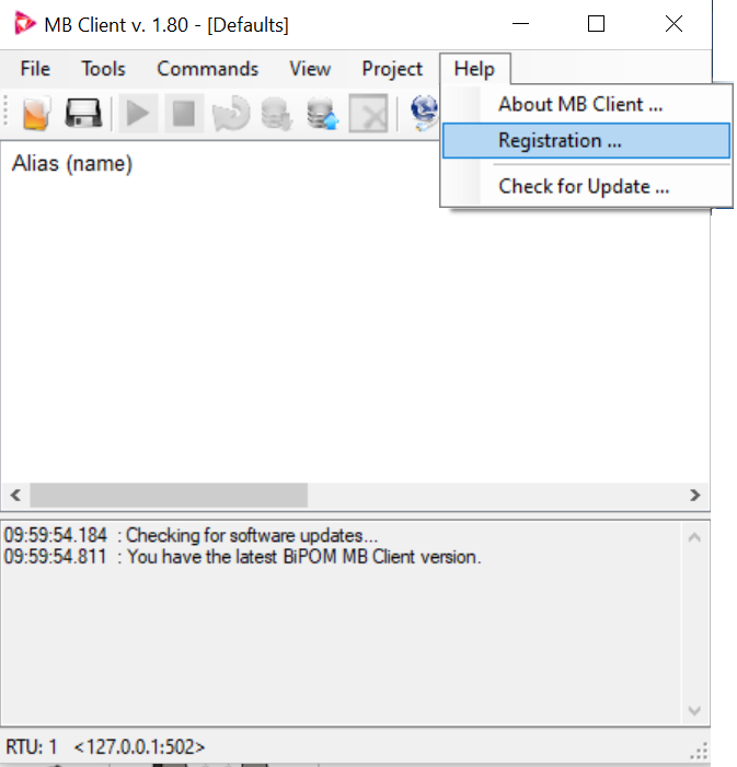
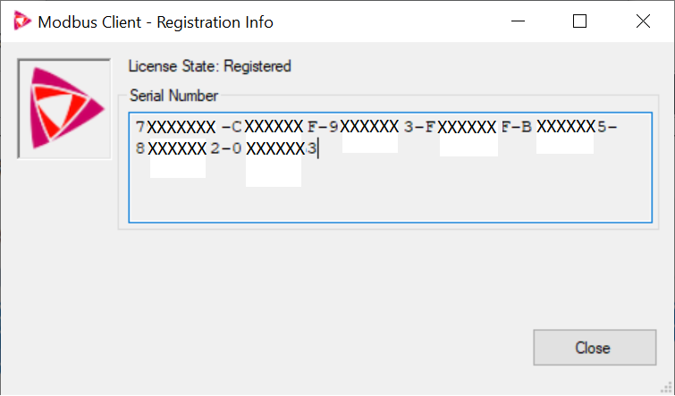
ITC Wiring Diagram

Wiring to a PC with DTech USB to RS485 Adapter
Link to Purchase Adapter:
https://www.amazon.com/Serial-Converter-Adapter-Supports-Windows/dp/B0195ZD3P4
