TwinProx - Modbus
A revolutionary and effective way to monitor, analyze and protect large machines with oil-lubricated bearings. A multi-drop Modbus RTU slave device.
Brochure


Specifications and Dimensions
Specifications
| Power | +24VDC (7 to 36 Volts full range) @ 60mA (default) |
| Channels | 2 |
| Input | 2 API670 style non-contact proximity probes |
| Output | Vibration displacement peak to peak (microns or mils) Axial thrust position distance (microns or mils) 360° phase reference (analysis) Speed (rpm or cpm or Hz) |
| Communication Protocol | Modbus RTU Baudrate: 115200 Parity: None Handshakes: None Data Bits: 8 Stop Bits: 1 |
| Temperature Range |
Standard: -40°F (-40°C) to +185°F (85°C)
High-Temperature Option: +212°F (+105°C) *Consult Factory for High Temperature Applications |
| Mounting Options | 35mm DINrail Baseplate + Fastener |
| Display / Indicators | 3 high intensity, multi-color LEDs (system and probe status) |
| Enclosure | PBT (Thermoplastic Polymer Blend) |
|
Hazardous Area Approvals |
CSA, cUL, IECEx, Class I Division 2 Groups A-D (pending) CE and RCM (pending) |
|
Ranges |
80 mils (2032 microns) 160 mils (4064 microns) 160 mils (4064 microns) |
|
Compatible Probe Series |
3300 8mm 3300 11mm (option) 3309 Focus View 5mm |
|
System Lengths |
1 meter 5 meter 7 meter (Focus View only) 9 meter * Consult factory for custom system lengths. |
| Target Materials |
Standard: ASTM 4140
*Consult factory for other target materials |
| Accuracy | +/- 2% of full scale |
| Linearity | +/- 1 mil best straight-line fit |
|
Resolution |
0.0002” (5um) |
|
Frequency Response |
0 – 5,000Hz |
| A/D Sample Rate | 16 bits |
| Speed Measurement Range | 300,000 CPM |
|
IP Rating |
IP64 |
| Humidity | 99% condensing |
| Terminals | > 15 Newton hold force |
| Alarms |
Low Low Low High High High |
| Programmable | TwinProx ship configured based on user preferences. All functions can be set using the user interface software. |
| Weight | 4.8 ounces (136 grams) |
Dimensions
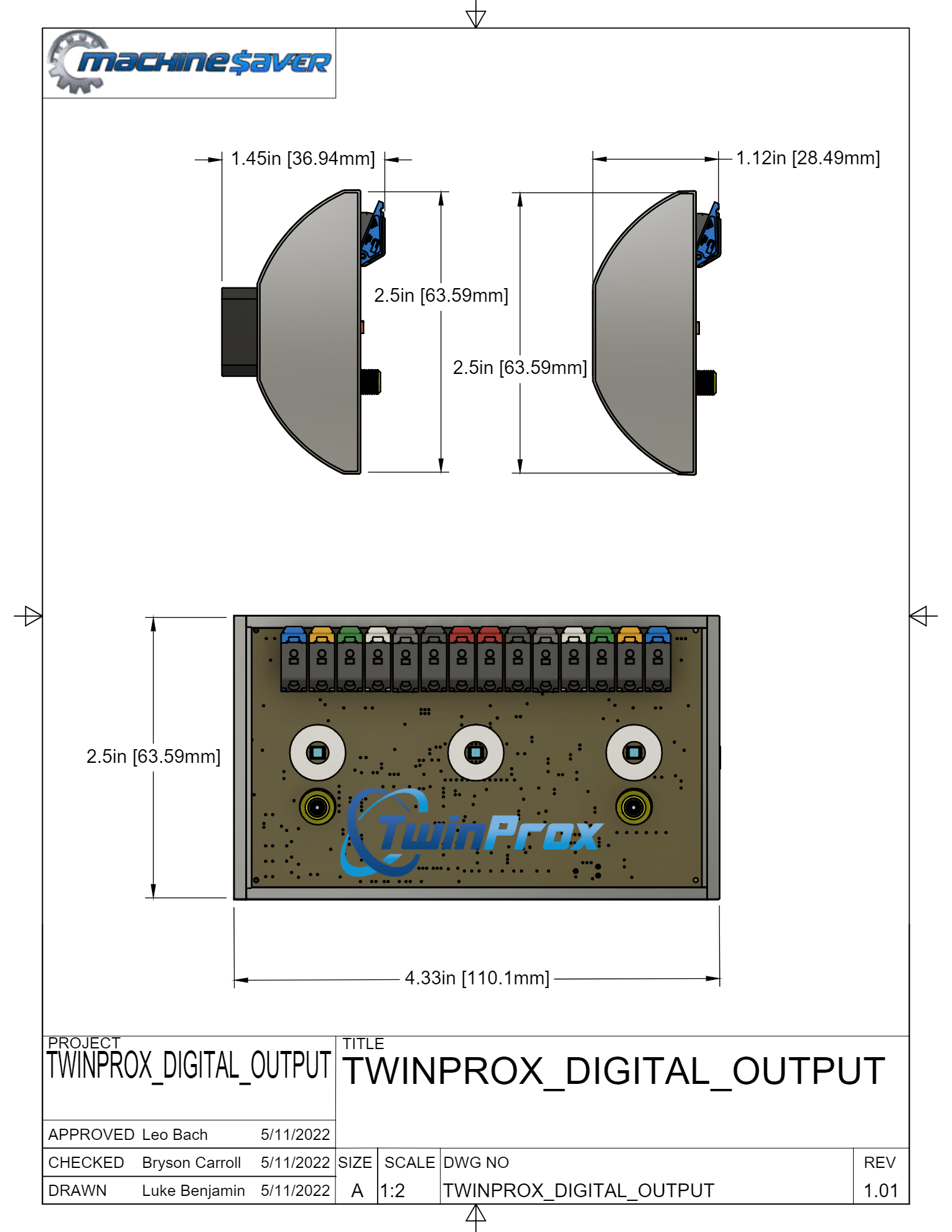
Figure 1: Dimensional Drawing
Ordering
How to Order
| Product Code | Channel A Application | Channel B Application | Probe Series and Tip Diameter | System Length | Special Application |
| 2PRX | AA | BB | C | D | EE |
*2PRX refers to TwinProx model prefix.
Channel A and B
| AA | Application for Channel A |
00 = Vibration (Default) 01 = Phase Reference Probe 02 - 255 = Speed (Number of Gear Teeth or Notches) ZZ = Axial Thrust Position |
| BB | Application for Channel B |
00 = Vibration (Default) 01 = Phase Reference Probe 02 - 255 = Speed (Number of Gear Teeth or Notches) ZZ = Axial Thrust Position |
Probe Series and Tip Diameter
| C |
0 = 3300 8mm (Default) 1 = 3300 11mm 2 = 3309 5mm Focus View |
System Length
| D |
5 = 5 Meter (Default) 1 = 1 Meter 7 = 7 Meters 9 = 9 Meters |
Special Application
| E | 00 = No Special (Default) |
Installation
TwinProx Universal Proximity System (Installation Manual)
TwinProx_MB
TwinProx_VO
Installation Manual
The TwinProx family consists of 2 devices, the TwinProx_MB and the TwinProx_VO.
Both the TwinProx_MB and TwinProx_VO are dual channel proximity transmitter system which allows users to use a variety of probe and extension cable combinations (from a variety of traditional manufacturers) without the hassle of using specific drivers and transmitters for each series, tip diameter and extension cable length. The TwinProx_MB and TwinProx_VO both are capable of being setup using an intuitive user interface via an RS485 connection to a computer. All functions are also settable using Modbus read/write commands from any Modbus master. The TwinProx_VO provides a voltage output so customers used to the Proximitor or Probe Driver interface may continue operating within their comfort zone for alarms and shutdown.
Safety Terms and Symbols
Terns that appear in this manual requiring special attention include:
-
WARNING: Warning statements identify conditions or practices that could result in injury or loss of life.
-
CAUTION: Caution statements identify conditions or practices that could result in damage to the product, loss or corruption of data, or damage to the environment or other property.
-
NOTE: Notes identify material or special interest or importance to the user, not including caution or warnings.
Symbols that may appear on the product and/or this manual include:


General Safety Summary
Review the following safety precautions to avoid injury and prevent damage to this product or any products connected to it.
- Use Only as Specified
To avoid any potential hazards, use this product only as specified.
Only qualified personnel should perform installation and uninstallation procedures. - Observe All Terminal Ratings
To avoid fire or shock hazard, observe all ratings and markings on the product.
Consult the individual sections of this manual for further ratings information before making connections of product. - Avoid Exposure to Circuitry
Do not touch exposed electrical connections and components when power is present. - Do not Operate with Suspect Failures
If you suspect there is damage to this product, have it inspected by qualified personnel.
Receiving, Inspecting and Handling the System
Machine Saver ships the probe, extension cable, and TwinProx transmitters as separate units that the user interconnects at the installation site. Carefully remove all equipment from the shipping containers and inspect it for shipping damage. If you see shipping damage, file a claim with the carrier and submit a copy to Machine Saver Inc. Include part numbers and serial numbers on all correspondence. If no damage is apparent and the equipment is not going to be used immediately, return the equipment to the shipping containers and reseal until ready for use. Store the equipment in an environment that is free from any potentially damaging conditions such as extreme temperature, excessive humidity, or a corrosive atmosphere.
Overview
Machine Saver's TwinProx System comes in two versions:
- 2PRX-MB = Dual Proximity Transmitter. A Modbus RTU Slave for Setup and Modbus Output for Monitoring
- 2PRX-VO = Dual Proximity Probe Driver.
The following sections cover each of these in more detail.
2PRX-MB
The 2PRX-MB signal format is for use when vibration, axial position, rotational speed, or phase measurements will be directly connected to a Modbus Master (PLC, DCS, SCADA system) or other instrumentation
that accepts Modbus RTU (RS485) inputs.
It is powered by +24 VDC. Two optional wires for a private bus can be used with a monitoring system within 20 meters (65 ft) typically used when 360 degree phase analysis is required. The device is configurable to function as either a radial vibration transmitter (peak‐peak vibration displacement amplitude), as an axial position transmitter (with average displacement distance probe gap), as a rotational speed transmitter (shaft speed), and/or as a 360 degree phase analysis transmitter (syncs the analysis data from all the TwinProx devices on the same machine train --- private bus).
2PRX-VO - Wire Vibration / Position / Speed Transmitter
The 2PRX-VO signal output is compatible with industry-standard continuous-vibration monitoring systems and is the format specified in API Standard 670. It uses ‐24VDC excitation and provides the output signal in mV/mm, typically 7.87 mV/mm (200mV/mil) for 5 mm and 8mm probes and 3.94 mV/mm (100 mV/mil) for 11 mm probes.
Installation
Probe Installation
Mount the probe in a simple bracket in a tapped hole in the bearing cap or by means of a Reverse Mount Probe Housing. The latter arrangement provides an easy means to adjust the probe gap, especially where the target is some distance from the outside surface of the machine.
When inserting the probe into the machine please refer to the user interface Probe Gap instructions. If possible, set the probe gap while the machine is shutdown, to avoid the danger of damaging the probe in the event that it touches the shaft.
Connect the probe to the driver/transmitter using the proper extension cable. If a connector must be replaced, the overall length of the probe or extension cable can be reduced by 2” total without adversely affecting the calibration and linearity. Insulate the probe connector/extension cable connector junction with the connector insulator.
Radial Vibration Measurements
For radial vibration measurements, mount the probe perpendicular to the shaft with the
probe tip approximately 0.050” (1.25 mm) from the shaft surface. Provide the probe tip with
sufficient clearance from surrounding metal to prevent an erroneous output. As a minimum,
the clearance diameter should be 0.75” (19 mm) for the full length of the probe tip. See
Figure 1. You can set the probe gap “visually” to the center of its measurement range by
observing the LED color (reference the LED chart Figure) of the appropriate channel on the TwinProx or by monitoring Modbus registers associated with distance (user interface). The preferred static gap range is 0.030” to 0.050”. To prevent cross-feed between two probes mounted in the same vicinity, maintain a minimum 1.0” (25 mm) spacing between the probe tips. See Figure 2.
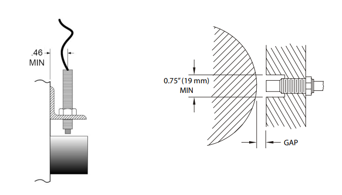 Figure_1
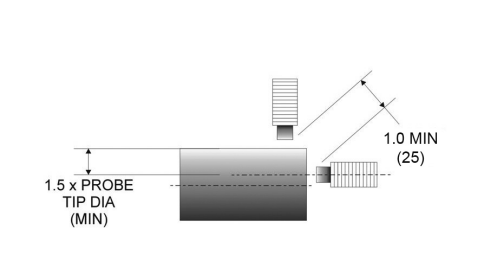
Figure_2
Axial Position / Thrust Measurements
For thrust measurements ensure the thrust range is within the probe range. Move the machine to ensure the thrust range is set properly within the probe linear range. For position (thrust) measurements, mount the probe with the probe axis parallel to the
shaft and with the probe tip approximately 0.050” (1.25 mm) from the end of the shaft. For 11 mm diameter probes, this distance is approximately 0.088”(2.2mm). Provide the probe tip with sufficient clearance from surrounding metal to prevent an erroneous output. As a minimum, the clearance diameter should be 0.75” (19 mm) for the full length of the probe tip. For an 11mm probe, the minimum clearance should be 0.88” (22 mm). See Figure 1.
You can set the probe gap “visually” to the center of its measurement range by observing the LED color (reference the LED chart Figure) of the appropriate channel on the TwinProx or by monitoring Modbus registers associated with distance (user interface). The preferred static gap range is 0.030” to 0.050”. To prevent cross-feed between two probes mounted in the same vicinity, maintain a minimum 1.0” (25 mm) spacing between the probe tips. For 11 mm probes, this distance is approximately
1.5” (38mm). See Figure 3.
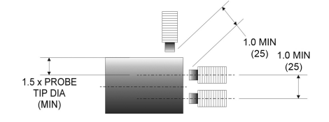
Figure_3
Speed Measurements
For RPM measurements, mount the probe with its axis radial to the shaft with its tip approximately 0.050” (1.25 mm) from the outermost surface of the shaft. The probe tip must be provided with sufficient clearance from surrounding metal to prevent an erroneous output. As a minimum, the clearance diameter should be 0.75” (19 mm) for the full length of the
probe tip. See Figure 4. To prevent cross-feed between two probes mounted in the same vicinity, at least 1.0”
(25 mm) spacing between the probe tips should be maintained. See Figures 5, 6.
The minimum keyway depth is 0.060” (1.5 mm). The minimum keyway width and key width
is the diameter of the probe tip (Figure 7). These minimums will ensure that the transmitter or driver responds properly to the keyway at all RPMs. Some experimentation may be required such as adjusting the min and max thresholds on the user interface, adjusting the probe gap, and/or modifying the keyway dimensions, or some combination thereof.
The probe can be mounted in a simple bracket, in a tapped hole in the bearing cap, or by means of a Reverse Mount Probe Housing. The latter arrangement provides an easy way to adjust the probe gap, especially where the target is some distance from the outside surface of the machine.
When inserting the probe into the machine please refer to the user interface Probe Gap instructions. If possible, set the probe gap while the machine is shutdown, to avoid the danger of damaging the probe in the event that it touches the shaft.
Connect the probe to the transmitter using the proper extension cable such that the combined system length of probe + cable matches the transmitter configuration. Do not change the length of the extension cable from the system, as such action will adversely affect the calibration and linearity. If a connector must be replaced, the overall length of the cable can be reduced by 2” without harm, we recommend using the linearity function from the user interface to verify any modifications to probe lengths or system lengths. Insulate the probe connector / extension cable connector junction with the connector insulator.

Figure_4
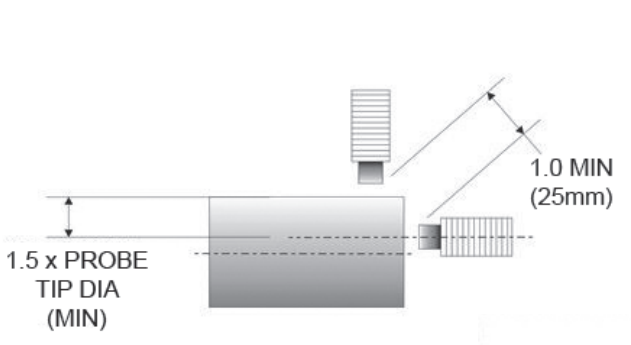
Figure_5
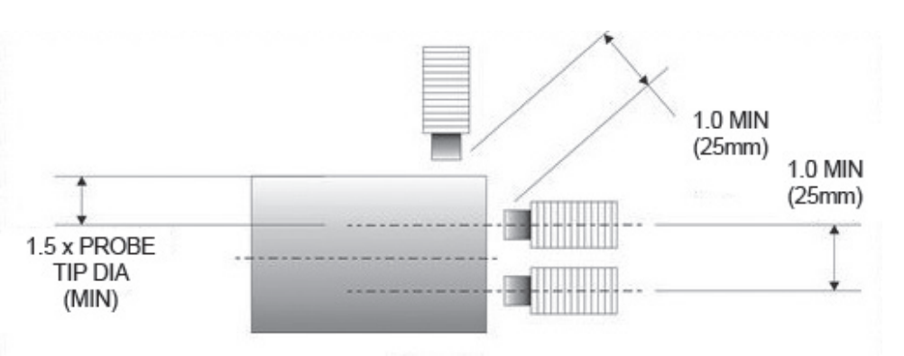
Figure_6
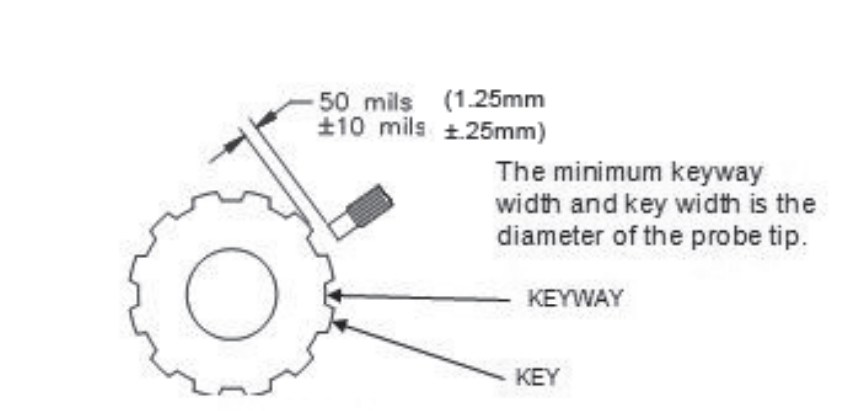
Figure_7
Extension Cable Installation
Route the extension cable using the following guidelines:
• Check that the TwinProx settings on the user interface are set to the actual:
Probe Type and Diameter
Extension Cable Length
Each should belong to the same series
• Secure the extension cable to supporting surfaces or places in conduit. Make certain the
cable is not kinked, scraped, nor bent beyond the minimum recommended radius of 1”.
• Secure coaxial connectors between the extension cable and the proximity probe. Connection should be “finger tight” with an additional quarter turn using an open ended 9/32” wrench or equivalent.
• Insulate the connection between the probe lead and the extension cable by wrapping the
connector with Teflon tape and the connector insulator. Avoid electrical tape for insulation because of its tendency to melt and detach over time.
Driver / Transmitter Installation
Mount the driver or transmitter in a suitable enclosure in a location that is compatible with
its environmental specifications. Refer to the datasheet for the environmental specifications.
The driver or transmitter comes with a 35mm DIN rail mount.
Field Wiring Methods
Proper Bend Radius
The wires going to the TwinProx should not be under any constant stress. Cut enough wire to
reach the TwinProx unit with a 1 inch (25 mm) bend radius and never stretch the wire for the connection.
Field Wire Preparation
Connect the field wiring (18 AWG - Power Pair, 20-24 AWG - Communication Pair, 20-24 AWG, 120 Ohm Impedance - Private Bus Pair) in accordance with the below diagrams. No prior preparation is required for solid core wire connecting to TwinProx terminals other than proper wire stripping. For stranded wires, it is recommended to use tinned strands. Tinned wires not only prevent accelerated corrosion against wet and contaminated environments, but also increase the strength of connection. The below diagram shows the difference between tinned and untinned wires.
Installation for Tinned or Solid Core Wires:
- Prepare: Strip the wire back 0.275 inches (7 mm) from the end of the stranded wire, and tin the wires so they become one piece using solder, like in the picture above. If using solid core wire no tinning is necessary, properly strip the wire. Ensure the tinned wire, or solid core wire, is flat at the end, if not, cut the end slightly with right angle wire cutters to make it flat. Strip additional insulation back, if necessary, to obtain, the 0.275 inches (7 mm) bare wire length.
- Push Button Connection: If using a push button connection, push down on the terminal lever, insert the 0.275 inches (7 mm) wire fully, release the terminal lever, and conduct a 2 pound (1 kg) pull test to ensure a secure connection. Do this with each wire. The color coded push button connectors are designed for 15 Newton, 3.3 lbs (1.5 Kg).
An alternative for stranded wire is to use a small connector ferrule (18 AWG) to facilitate the connection.
Installation for Stranded Wire using a Wire Connector Ferrule:
- Prepare: Strip the wire back 0.275 inches (7 mm) from the end of the wire.
- Insert: Slide the stripped end into the connector.
- Crimp: Use an appropriate crimping tool to crimp the connector and the wire together (please note the area to crimp is on the pin).
- Installation: If using a color-coded push button connection, push down on the terminal lever, insert the connector pin fully, release the terminal lever, and conduct a 2 pound (1 kg) pull test to ensure a secure connection. Do this with each wire. The color coded push button connectors are designed for 15 Newton, 3.3 lbs (1.5 Kg).
Installation for Stranded Wires that are not Tinned:
- Prepare: Strip the wire back 0.275 inches (7 mm) from the end of the stranded wire, like in the picture above. If you are using stranded wire that is not tinned, be sure to twist the wires, to ensure all of the wires enter the connector. Check that the wire end is flat, if not, cut the end slightly with right angle wire cutters to make it flat. Strip additional insulation back, if necessary, to obtain the 0.5 inch (13 mm) bare wire length. All of the strands of wire should go to the bottom of the connector.
- Push Button Connection: If using a push button connection, push down the terminal lever, insert the 0.315 inches (8 mm) wire fully, release the terminal lever, and conduct a 2 pound (1 kg) pull test to ensure a secure connection. Do this with each wire. The color coded push button connectors are designed for 15 Newton, 3.3 lbs (1.5 Kg).
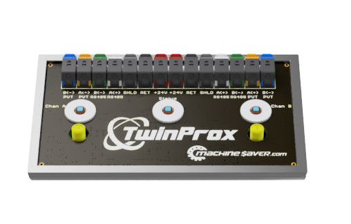
2PRX-MB Field Wiring Installation

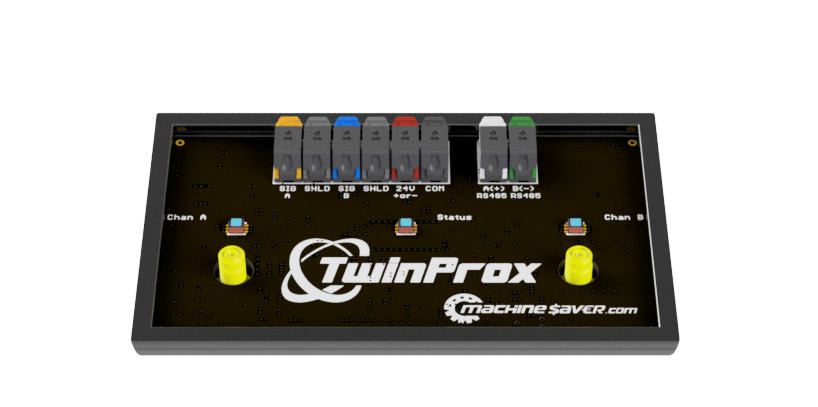
2PRX-VO Field Wiring Installation

Hazardous Area Installations
Special Conditions of Safe Use
Mount the TwinProx in a separate enclosure capable of withstanding a 7 joule impact and providing a minimum ingress protection of IP54.
The TwinProx cannot be repaired in the field. Replace a failed TwinProx with with an equivalent unit.
Do not expose the TwinProx to dust conditions.
Do not install the TwinProx where it may be subjected to mechanical and excessive thermal stresses or where it may be attacked by existing or forseeable aggressive substances.
Install the TwinProx such that its terminals are protected to at least IP20.
Protect the plastic TwinProx enclosure from impact and friction.
WARNING: TO PREVENT IGNITION OF FLAMMABLE OR COMBUSTIBLE ATMOSPHERES, DISCONNECT POWER BEFORE SERVICING.
WARNING: TO PREVENT IGNITION OF FLAMMABLE OR COMBUSTIBLE ATMOSPHERES, READ, UNDERSTAND, AND ADHERE TO THE MANUFACTURER'S LIVE MAINTENANCE PROCEDURES.
CALIBRATION AND SIGNAL ANALYSIS
General
Factory calibrated units are for use with the specified probe, extension cable and target part numbers. Use the User Interface software to configure un-configured units before putting into service. For maximum accuracy, calibrate the driver with the probe
and cable to be used.
CAUTION: Do not connect test equipment or cables to the driver unless the area has been determined to be non-hazardous.
Environmental Information
This electronic equipment was manufactured according to high quality standards to ensure safe and reliable operation when used as intended. Due to its nature, this equipment may contain small quantities of substances known to be hazardous to the environment or to human health if released into the environment. For this reason, Waste Electrical and Electronic Equipment (commonly known as WEEE) should never be disposed of in the public waste stream. The “Crossed-Out Waste Bin” label affixed to this product is a reminder to dispose of this product in accordance with local WEEE regulations. If you have questions about the disposal process, please contact Machine Saver Inc. Customer Service.
All trademarks, service marks, and/or registered trademarks used in this document belong to Machine Saver Inc. except as noted below:
© 2023, Machine Saver Inc. All rights reserved.
5-11-2023
Software
TwinProx Universal Proximity System (Software Manual)
TwinProx User Interface Version 1.0.5
TwinProx User Interface Release 5
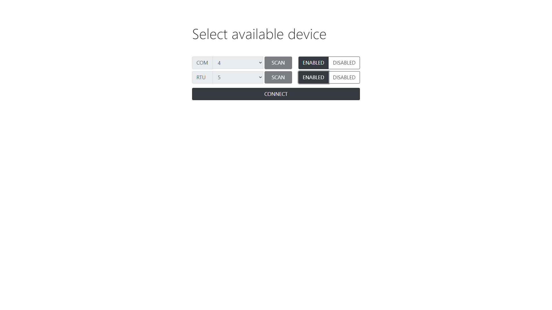
Connecting to TwinProx

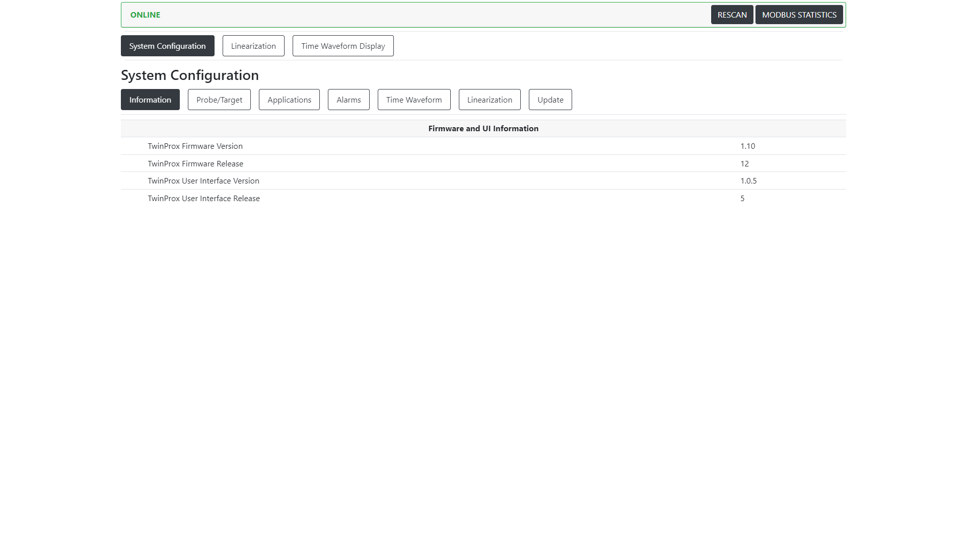
Configuring TwinProx
Information - shows the hardware and software revisions.
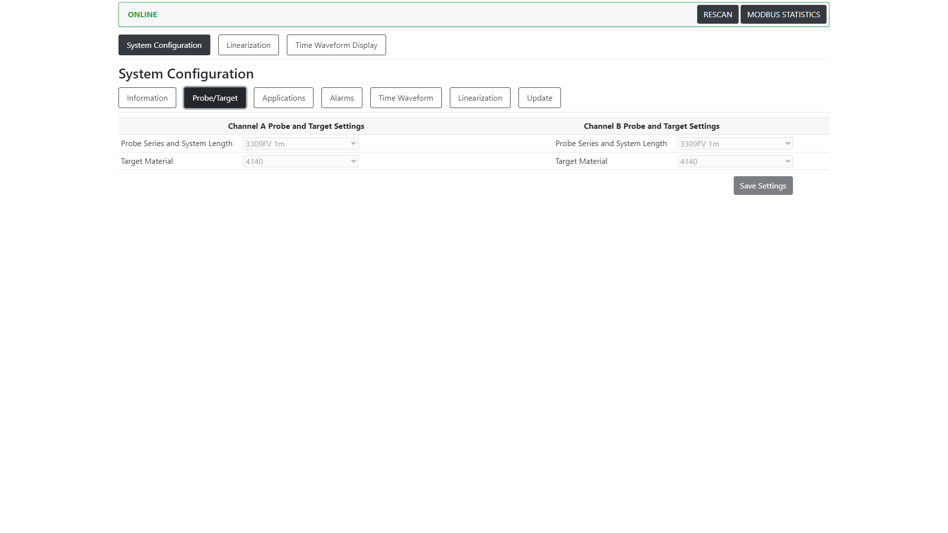
Probe/Target - Allows user to define the probe series, length and target materials.
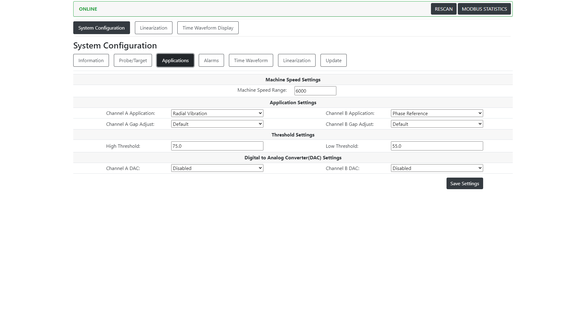
Applications - Allows user to define the application and relevant settings for that particular application for each channel/probe.
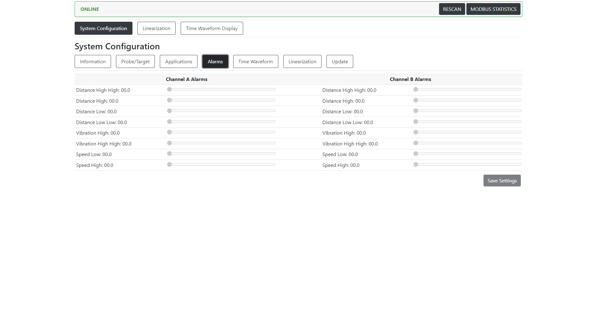
Alarms - Allows user to define the alarms relevant to the selected application.
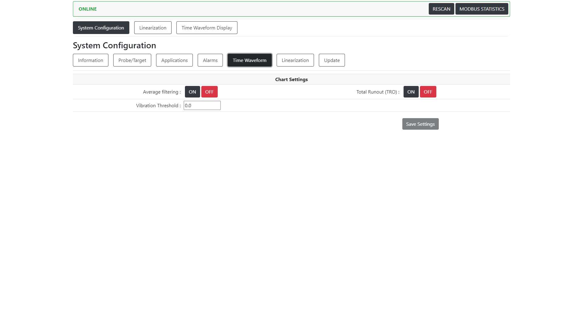
Time Waveform - Allows user to add filtering, total runout compensation and a vibration threshold which effect the output on the Time Waveform Display Tab.
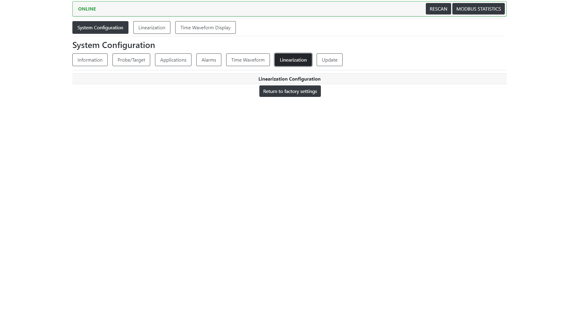
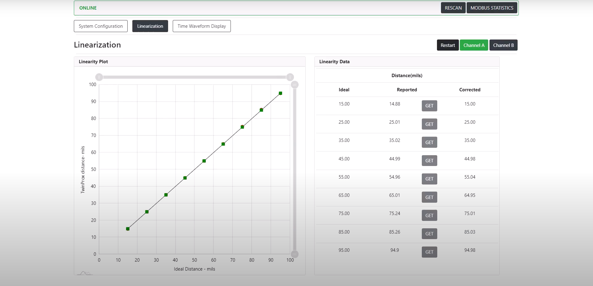
Linearization - Returns any changes made to the linearization of a channel to original factory settings.
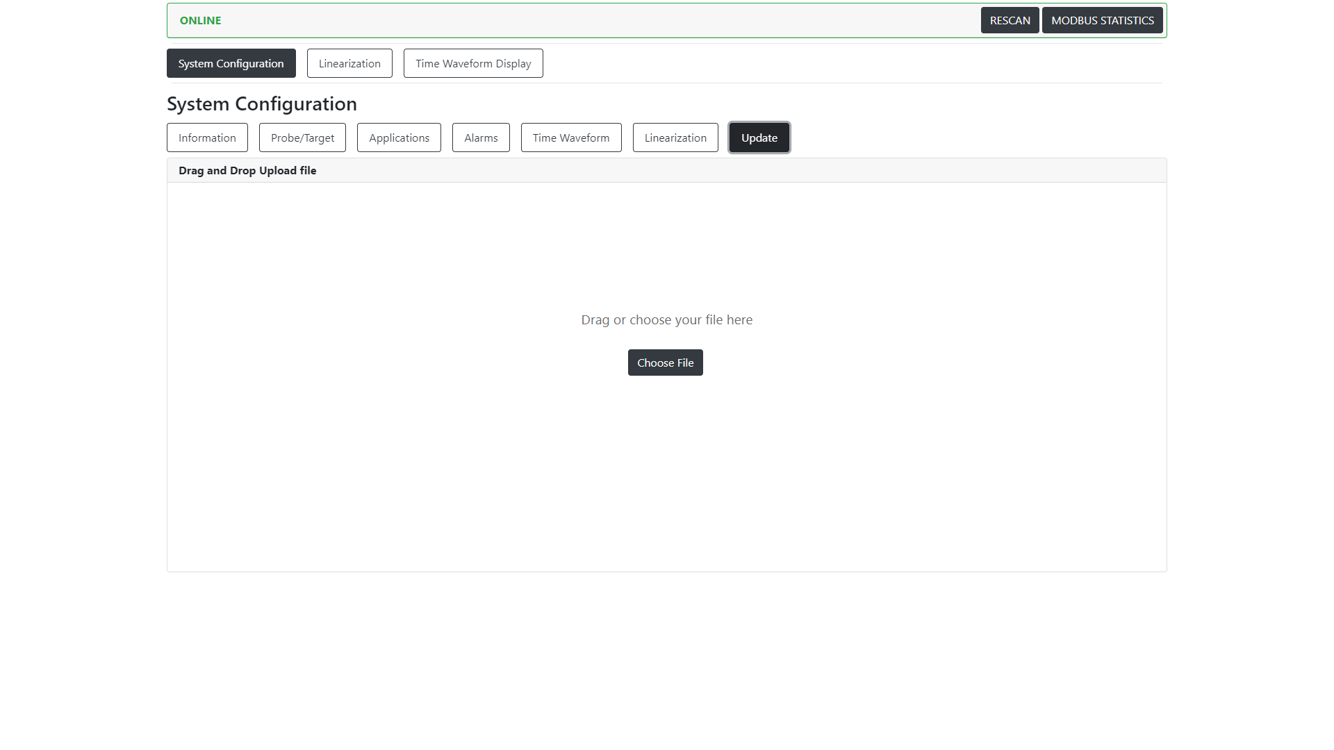
Update - Allows for a user to upload new firmware to the connected TwinProx hardware.
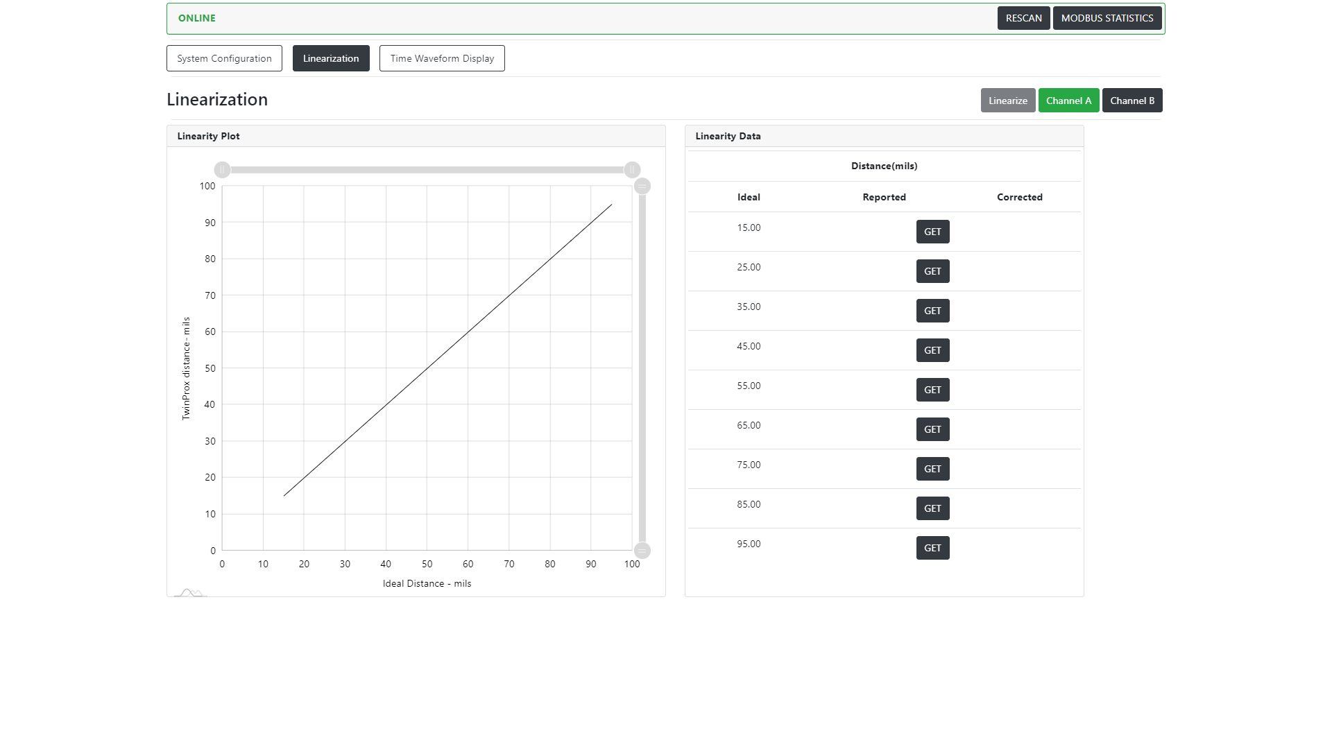
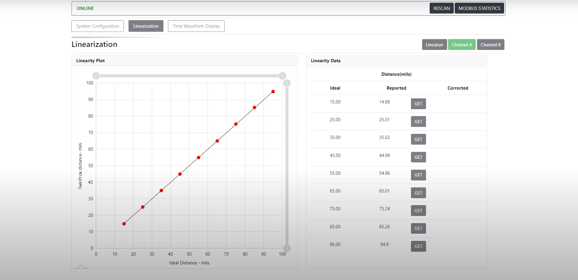
Linearizing (Verification) of TwinProx
Channel A Example:
Video Example:
Waveform and Orbit from TwinProx
Starting the Live Waveform and Orbit
Select the channels that you would like to see data from, click the play button.
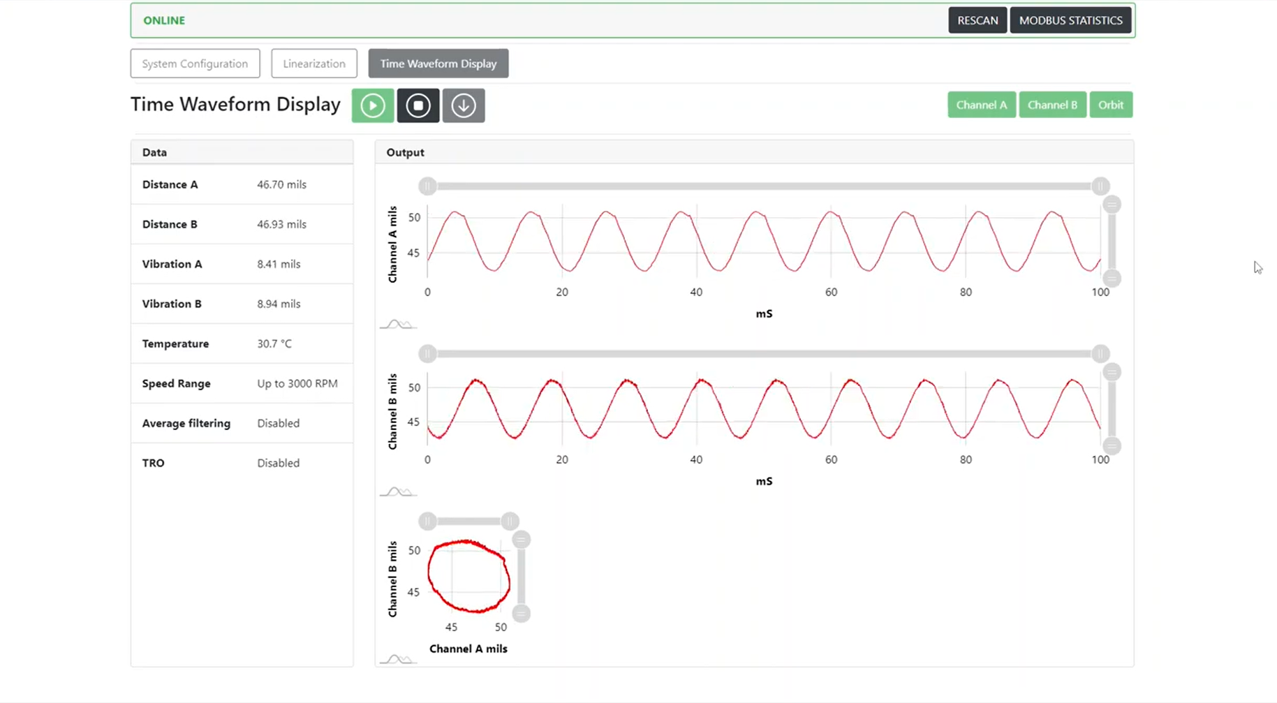
Stopping the Live Waveform and Orbit
Click the stop button.
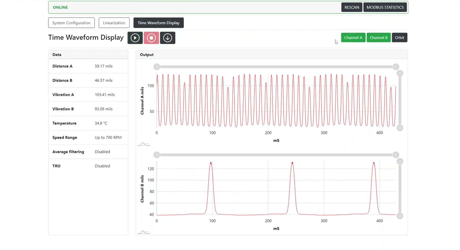
Downloading the Last Frame of Waveform and Orbit
After clicking the stop button, you can click the download button to save a CSV of the last waveform and orbit data captured.
The CSV also contains a timestamp and configuration parameters of the TwinProx and Channel settings.
All trademarks, service marks, and/or registered trademarks used in this document belong to
Machine Saver, Inc.
© 2023, Machine Saver, Inc. All rights reserved.
Integration
Analysis Data Waveform and Orbit Theory
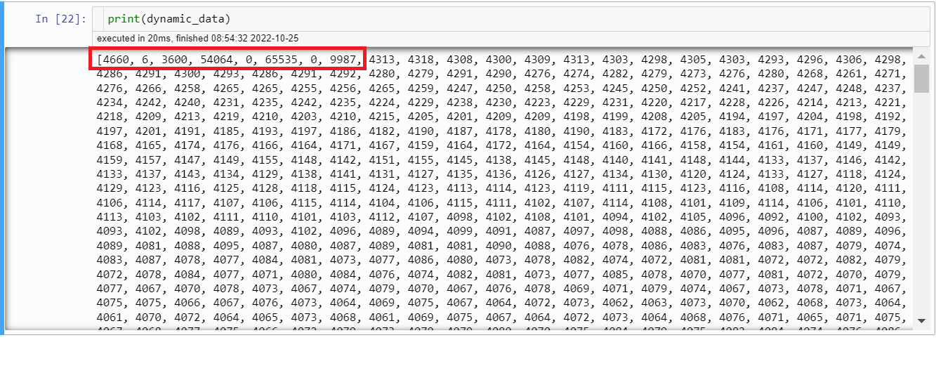
Header structure is the following:
- First register contains signature
- Second register contains type
- Third register contains data array size
- Fourth register contains data array CRC
- Fifth register contains groove array size
- Sixth register contains groove array CRC
- Seventh register is reserved
- Eight register contains CRC of the header
In your example:
4660 = 0x1234 is the correct signature
6 is type
3600 is the size of the data array
54064 is CRC of the 3600-sample data array
0 is the size of the groove indexes array (this indicates that you did not have any notches)
65535 is CRC of the groove array( which you do not need to calculate in your case because you did not have any notches)
0 is just a reserved member of header, we do not use it for now. We allocated it for later in case if we ever need to place something else in header.
9987 is crc of the header.
Orbit Plots: DataClipSamples.xlsx
Above is a computer-generated signal in excel.
I used it to check whether our ideas with notch functionality would work.
This describes the process of getting from two sinewaves to an orbit signal.
I replaced 1800 Ch A data clip samples with 1800 samples of perfect sin wave.
Likewise, 1800 Ch B data clip samples with 1800 samples of perfect cos wave.
The computer-generated signal created perfect looking orbit, so we could test our notch functionality.
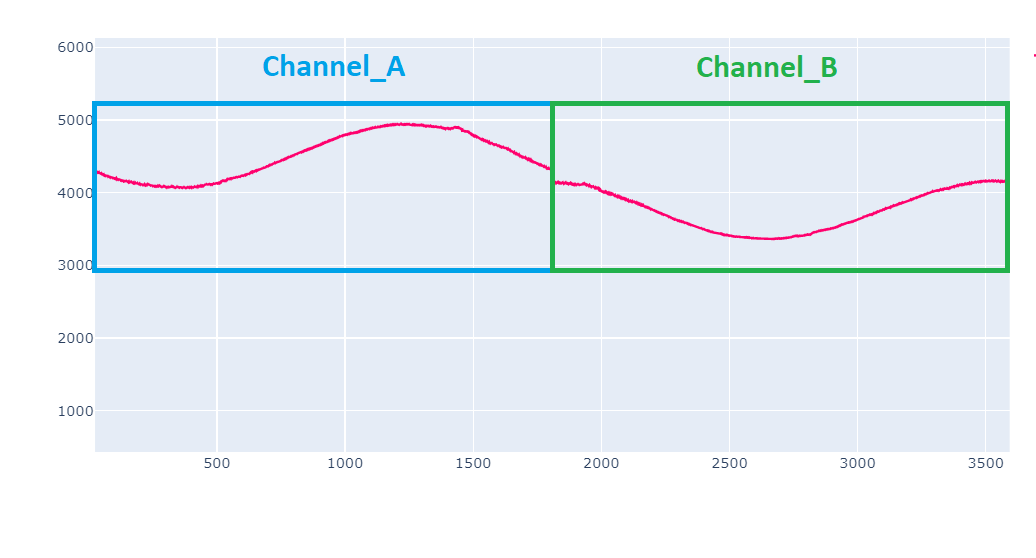
As for combining two data charts into orbit, you simply set MODBUS CHANNEL NUMBER REGISTER 40033 to MODBUS_CHANNELS_AB command.
This will capture data from both channels.
Data array size will be 3600 samples.
First 1800 samples are ch A samples.
Next 1800 samples are ch B samples.
So, it is easy to separate them.
Then you just plot channel A against channel B and you will get your orbit.
Modbus Register Map
About these Registers:
DEVICE_ID / REMOTE_TERMINAL_UNIT (RTU) / SLAVE_ID:
Each sensor on a single multi-drop bus line must have a unique DEVICE_ID / RTU / SLAVE_ID:
By Default the DEVICE_ID / RTU / SLAVE_ID is the LAST 2 DIGITS OF THE SENSORS SERIAL NUMBER
The serial number (and therefore, the RTU number) can be found on the side of the TwinProx on the white label.
INDEXING:
Note that the listed registers below are considered 0-Indexed (the first value starts at 0)
Some Modbus masters will need to shift all the values up by one value if their master recognized the first Modbus value at 1 (known as 1-indexed).
SERIAL COMMUNICATION SETTINGS:
Baudrate: 115200
Parity: None
Handshakes: None
Data Bits: 8
Stop Bits: 1
FUNCTION CODES:
The function codes supported by TwinProx Sensor are:
03 - (0x03) READ MULTIPLE HOLDING REGISTERS
16 - (0x10) WRITE MULTIPLE HOLDING REGISTERS
--- If you want to read or write to just a single register, you can do this by setting the length/offset/number of registers to 1 ---
Endianness:
The TwinProx sensor uses the Big Endian memory allocation paradigm.
In computing, endianness is the order or sequence of bytes of a word of digital data in computer memory. Endianness is primarily expressed as big-endian (BE) or little-endian (LE). A big-endian system stores the most significant byte of a word at the smallest memory address and the least significant byte at the largest. A little-endian system, in contrast, stores the least-significant byte at the smallest address.
Modbus Register Map
| Register Address | Number of Registers | Register Contents Description | Range | Default Value | Scale | Unit | Data Type | Read / Write | Notes |
| 40176 | 1 | Channel A Gap / Distance | 0 to 105 | n/a | value/100 | mils | 16-bit Unsigned Integer | R | |
| 40177 | 1 | Channel B Gap / Distance | 0 to 105 | n/a | value/100 | mils | 16-bit Unsigned Integer | R | |
| 40178 | 1 | Channel A Displacement | 0 to 105 | n/a | value/100 | mils Pk-Pk | 16-bit Unsigned Integer | R | |
| 40179 | 1 | Channel B Displacement | 0 to 105 | n/a | value/100 | mils Pk-Pk | 16-bit Unsigned Integer | R | |
| 40049 | 1 | DDC_START_SAMPLE | n/a | n/a | sample index | 16-bit Unsigned Integer |
R/W |
This register will start by reporting a 0 when read (indicating the 0th sample is in register 50, ready to be read). After successfully reading the data clip sample in register 171, this register should read 122 (indicating the 122nd sample is in register 50, ready to be read). |
|
| 40050-40171 | 122 | DDC_Samples | n/a | n/a | 16-bit Unsigned Integer |
R |
Block reads of registers 49 - 171 repeatedly until SAMPLES collected equal 1800. |
||
| 40171 | 1 | Auto_Reload_DDC_Chunk | n/a | n/a | 16-bit Unsigned Integer |
R |
Each time register 171 is successfully read by a Modbus Master. Register 49 is updated to reflect the index of the sample in register 50 and the next set of DDC Samples is loaded into registers 50 - 171. |