Specifications & Features
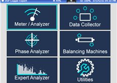
Data Collector is a six channel, route-enabled instrument that provides everything you need for cost-effective data collection and analysis. It enables maintenance professionals to easily take recordings with up to 25,400 lines of resolution and over 95 dB dynamic range.
Key features:
- 6 channels recordings
- Up to 25,400 lines FFT resolution
- 20 kHz Fmax
- 8 GB memory - Virtually unlimited spectra storage
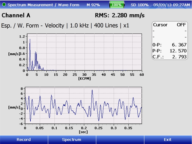
- Spectrum and Waveform recordings
- Cable Test mode
- Wi-Fi support
- Multi-location polling
- Route-equipment-point-measurement
- Route visualization tools
- Route regeneration of unmeasured points
- Route history, including last 5 captures
- Mechanical status tools
- Equipment diagram
- Equipment pictures
- Automated function: quick or detailed
- Alarm system in spectrum or scalar
- Manual measurement status system

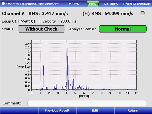
Vibration Meter and Analyzer

Bearing Measurement
- Bearing Condition
- Lubrication
- High Peaks
- Trending
Spike Energy®
- Amplitude by failure frequencies
- Spike Energy® State
- Trend
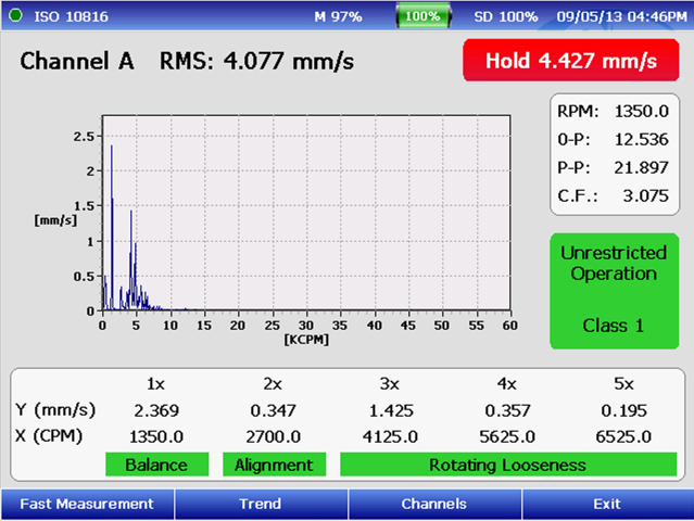
ISO 10816 Measurement
- ISO 10816 Status
- Balancing Status
- Alignment Status
- Looseness Status
- Trend
Dual Channel
- Bearing Condition
- Mechanical, ISO Condition
- Dual channel recording Function
Preconfigured Spectral Measurement
- Velocity
- Displacement
- Acceleration
- Envelope
Configurable Spectrum Measurements
- With Accelerometers
- With proximiters
- With Velocimeters
- AC
Triaxial Spectral Measurements
Dual Channel Scalar Measurements
Scalar Multi-variable Measurement
Tachometer RPM Measurement
Mechanical Status Tools
- ISO 10816 Status, Balancing Status
- Alignment Status, Looseness Status
Balancer

The dual-channel Balancer unbalance correction instrument is lightweight, making this instrument easy to carry on site to any problem machine. Unbalance causes high levels of mechanical stress and vibration. This is transferred directly to the bearings, resulting in a proportional reduction in normal bearing life.
With a few basic parameters, Balancer calculates acceptable unbalance levels to ensure machinery operates within international ISO 1940 guidelines.
- Single Plane Balancing
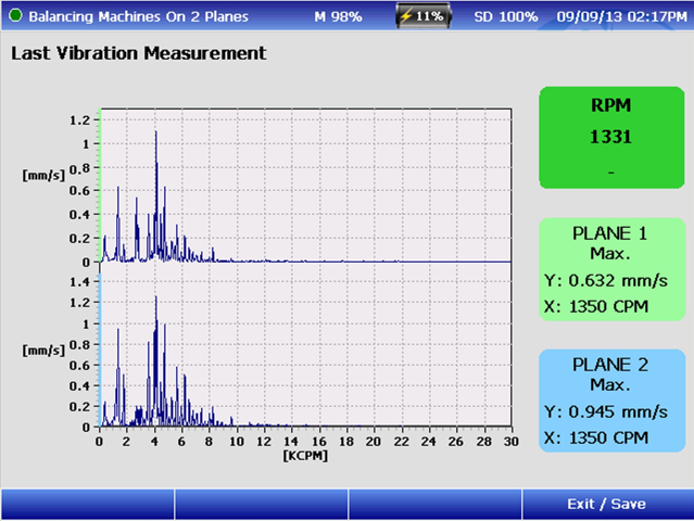
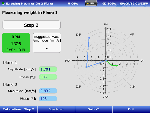
- Dual Plane Balancing
- No-Phase Balancing
- Dual Channel spectrum
- Calculations to add or subtract weight
- Final Correction Report
- Report Generator
Vibration Phase Analysis
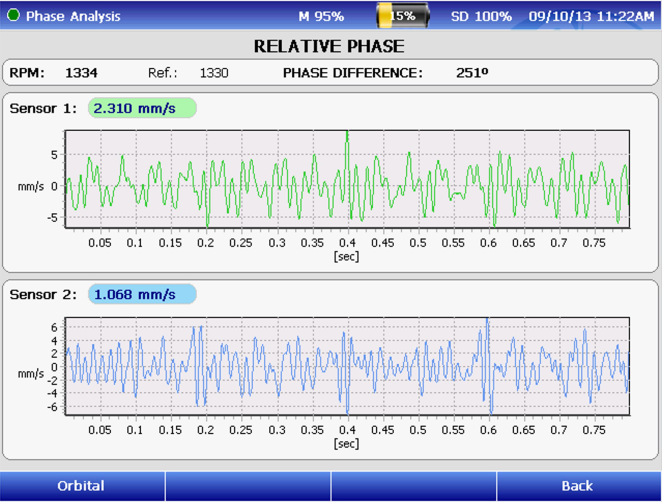
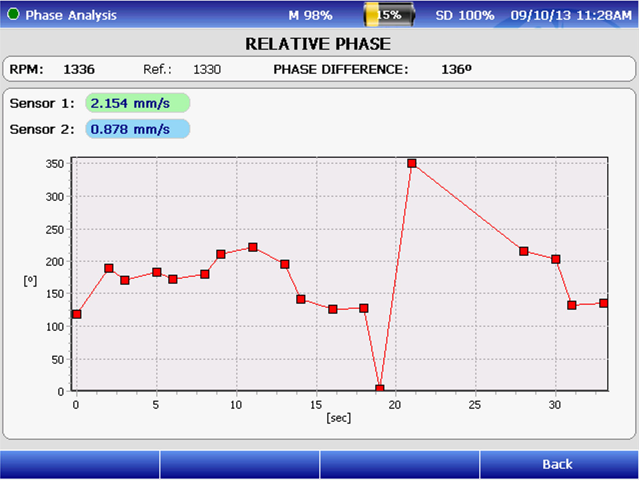
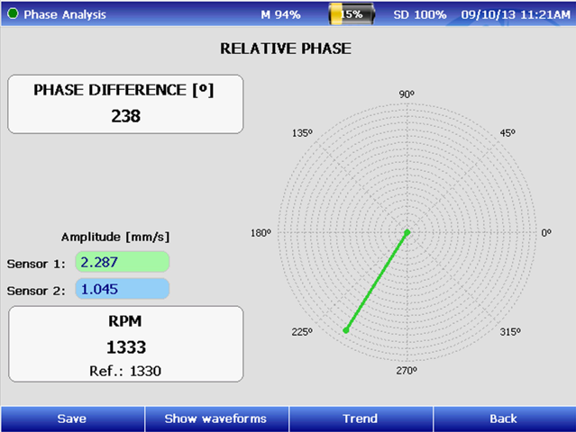
The phase analysis function only requires some parameters, the equipment name and estimated RPM. With this data, the system tunes the filters needed to perform phase analysis. The application screen clearly shows the RPM of the equipment analyzed in real time. The vibrational values of each point in RPM speed and 0-Peak, also include a polar plot indicating the position of the
measured phase.
Relative Phase Measurement
Absolute Phase Measurement
Samples to measure and position sensors
Includes:
- Polar Graph
- Phase Trend
- Dual Channel WaveForm
Control and Analysis Software
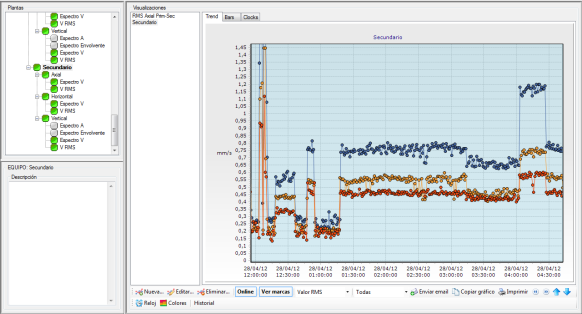
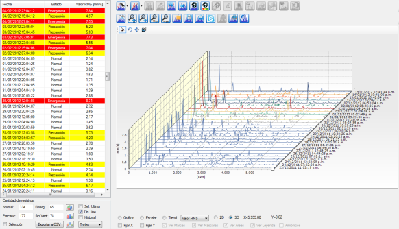
DSP Machinery Control software is designed for the organization and visualization of remote measurements delivered by remote monitoring WRM equipment and DSP Logger Expert Data collector. Measurement system thresholds, parameters and detailed analysis of results will be easily operated from this software.
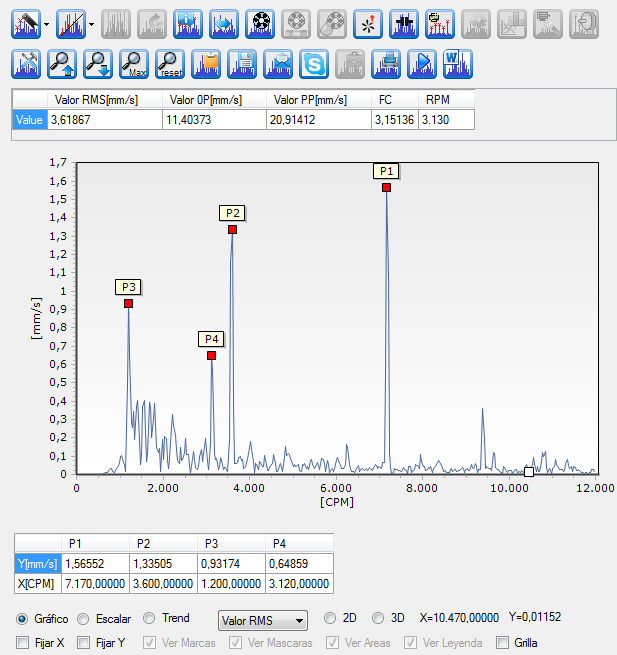
Tools for Analysis:
- Amplitude and frequency of a component.
- Highest peak locator.
- Harmonics locator.
- Bands locator.
- Frequencies of bearing failure.
- Harmonic frequencies of bearing failure.
- Configuration of tools and thresholds.
- Recording of spectrum as a JPG image file.
- Spectrum browsing based on dates.
- Alarm mask configuration based on historical spectra.
- Frequency and amplitude measurement unit converter.
- Automatic marker for characteristic failure frequencies.
- Automatic marker for gear frequencies.
- Automatic marker for belt frequencies.
Points can be configured, and standard and special measurements, and measurement samplings can be defined in case they are not configured as a monitoring routine procedure.
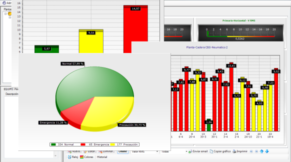
The multiple setting and point control tools allow the user to have full access to every variable that needs to be measured in order to isolate any failure the monitored equipment may be presenting.
The system delivers all tools for an operator at the control console to visualize the general status of vibrations on a critical machine and, at the same time, for an analyst to be able to diagnose based on the interpretation of vibrating signals using spectra,
waveforms, and analysis tools.
Technical Specifications
Input channels: Six
Input sources: Acceleration, AC/DC sensors
Amplitude accuracy: 1%
Resolution: Programmable: 400, 800, 1600, 3200, 6400, or 25600 lines
Measurement windows: Hanning, Flat top, Rectangular
Preprocessing gSE and ESP enveloping (demodulator) with four selectable input filters for
enhanced bearing and gear mesh fault detection
Digital Integration: Velocity and Displacement, with high-pass filters
Programmable 1%, 5% and 10% of Fmax filters:
- 1.25 to 2.5KHz
- 2.5KHz to 5KHz
- 5KHz to 10KHz
Frequency range: 0.2Hz to 20,000Hz
Low-frequency cutoff: 0.18Hz to 70Hz
USB Communication with SMP ActiveSync
Wi-Fi (optional)
Micro SD: 8GB
Trigger modes: Trigger: External or Laser Tach
Trigger Level: Fixed or Automatic
External Trigger Slope: Amplitude and Slope
Data Displays six-channel spectrum, six-channel time, phase table, orbit, process, cross
channel phase, dual spectrum, time plots, and two tri-axial plots
Averaging Programmable: 1 to 4096
Spectral, synchronous time, peak hold, and continuous
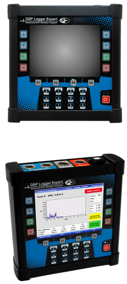
Display: LCD, backlit color
VGA (640 x 480) 5.7 ¨ viewable area
Casing: IP 65/DIN EN 60529 Aluminum
Input connectors:
- Connector A and Connector B are 5-pin AMPHENOL
- Connector A: Channel 1, 3 and 5
- Connector B: Channel 2, 4 and 6
- Microprocessor Nvidia DUAL CORE 1Ghz
- DSP processor Analog Devices
- Battery: Rechargeable lithium ion
- Weight, approx. 715 g (1.52 lb)
OPTIONAL: “Test I Go” Motor Current Signature Analyzer

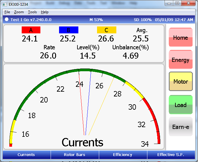
The Motor Current Signature Analysis (MCSA) “Test I go”
performs functions for predictive maintenance programs. It identifies possible power circuit
problems that degrade motor health, examines overall motor power conditions, monitors the
load and observes motor performance plus estimating energy savings.

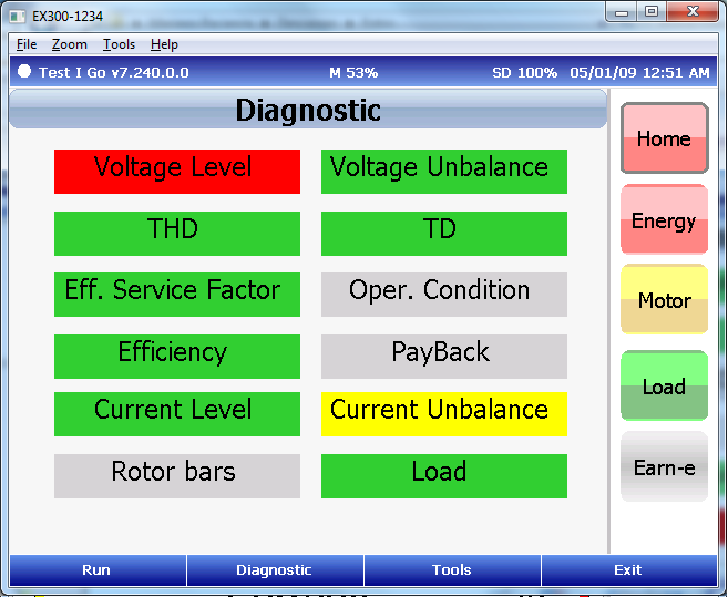
It is programmed to supply information on:
- Three phase voltage levels
- Voltage balance
- Harmonic distortion
- Rotor cage condition
- Motor efficiency
- Effective service factor
- Over-current
- Power factor correction
- Torque
- Load
Once testing is complete (ex.: 30 seconds), you can save and store results for each individual electric motor.
This is the only tool in the world capable of performing, also, a sophisticated; full 6 Channels
Mechanical Vibration Analysis. This avoids having to purchase two testers to perform Predictive
Maintenance for Industries with small number of motors, or, allows to buy a single platform unit
to integrate both mechanical and electrical analysis, for large industrial facilities with lots of
electric motors.
No Comments