ProxiTouch: User Manual
For Help With This Document:
Call Machine Saver Inc: +1(832)581-9908
or
Email: leo@machinesaver.net

Touch Screen PC Tips
One click of the finger is a left mouse click.
Holding down your finger is a right mouse click.
For full screen visibility of interface on the keyboard use [Fn] > [F11].
Exit full screen by right clicking and then selecting "Exit Full Screen".
Powering the ProxiTouch
- Plug in the power cord to a wall socket and turn the power switch to ON.
- This should power touchscreen PC and TwinProx.
- Please wait while the system starts up.
- The system should not take more than a minute to boot up.
Open TwinProx Dual Proximitor Graphical User Interface
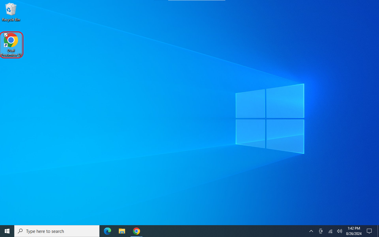
- The TwinProx User Interface can be opened by double clicking on the desktop icon labeled [Dual Proximitor UI].
Connect to TwinProx via User Interface
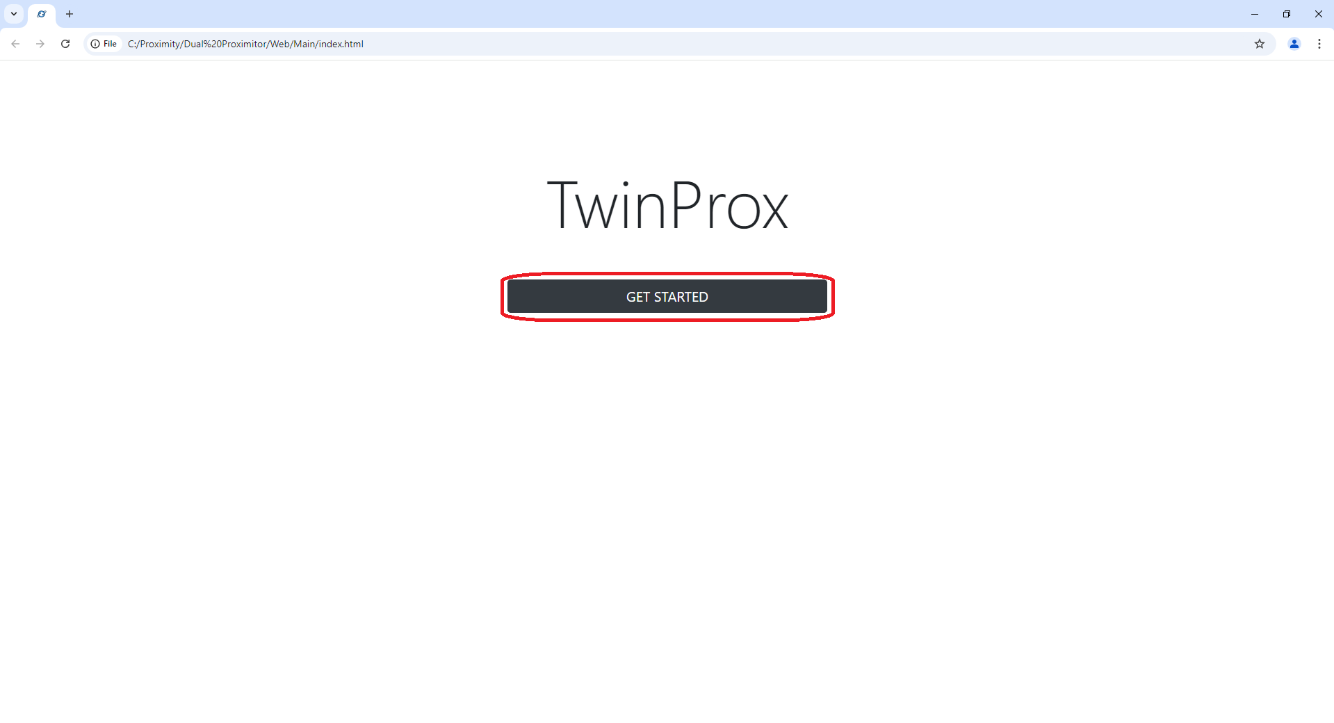
- Use the touchscreen to tap/click on the button [Get Started]
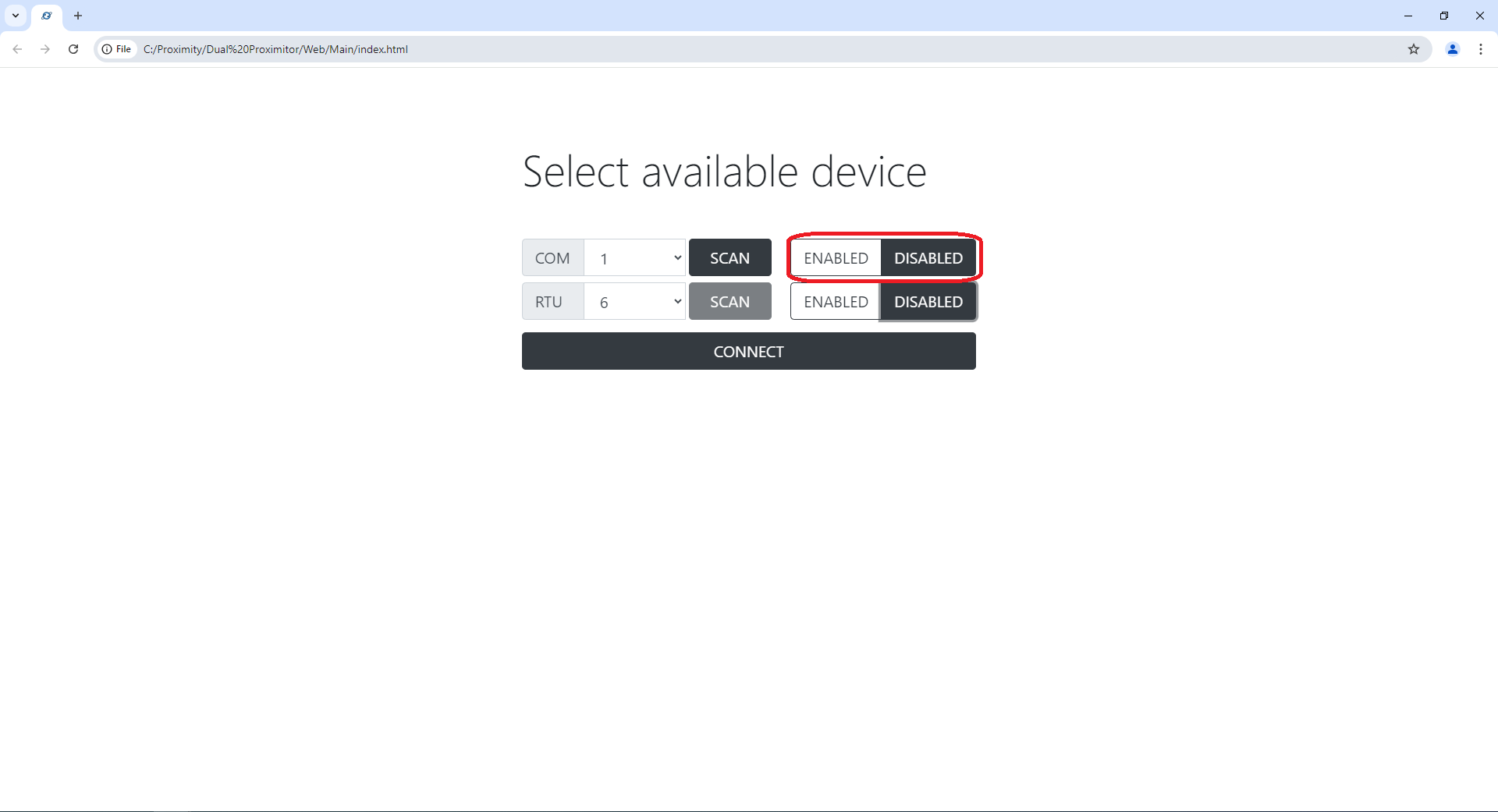
- COM should be set to [DISABLED] before using the COM [SCAN] button.
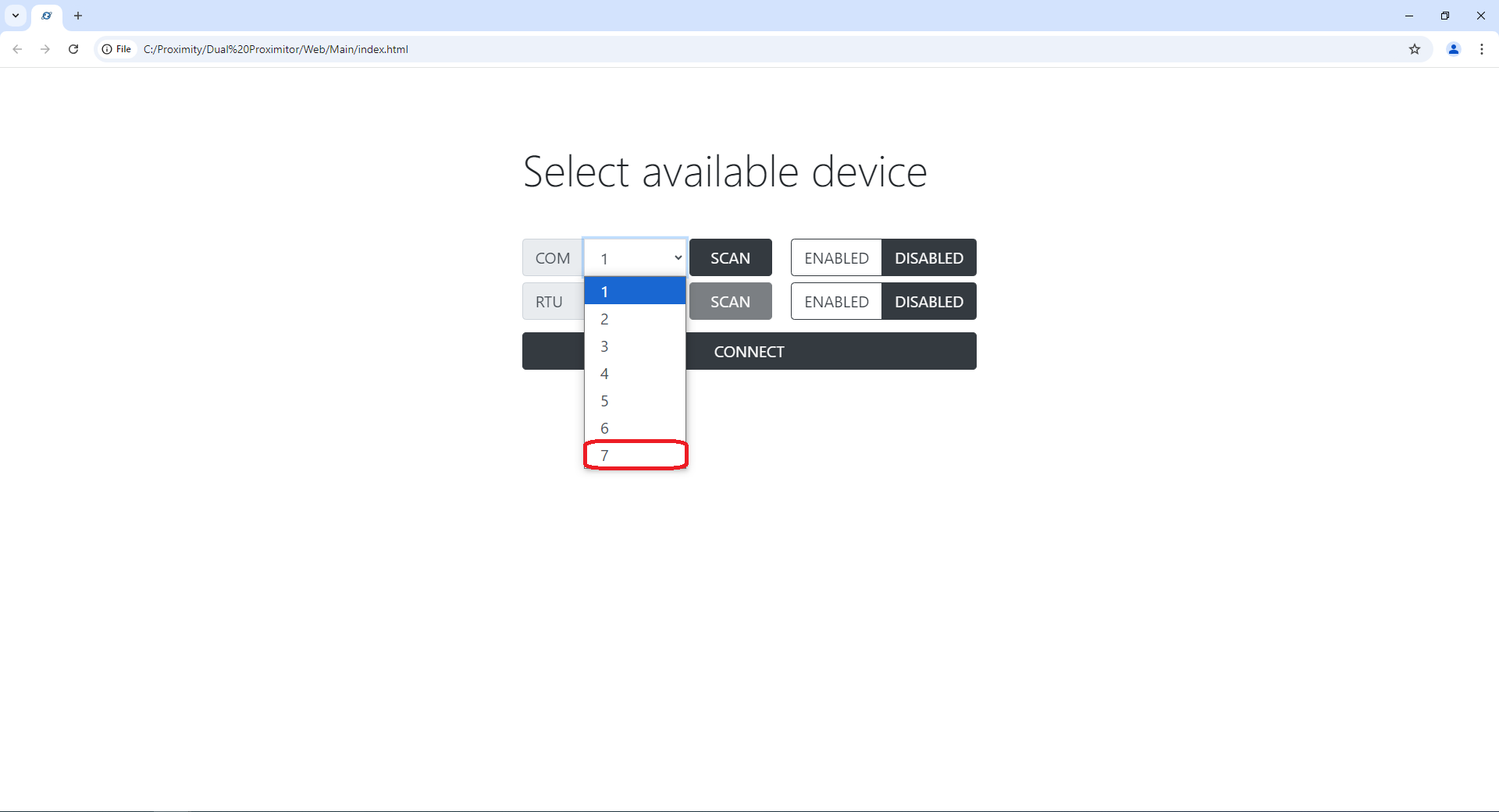
- After the scan is completed there should a populated dropdown menu next to COM.
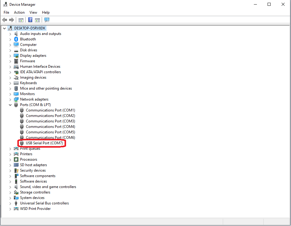
You should select the COM port that is associated with the USB Serial Port (RS485 to USB converter).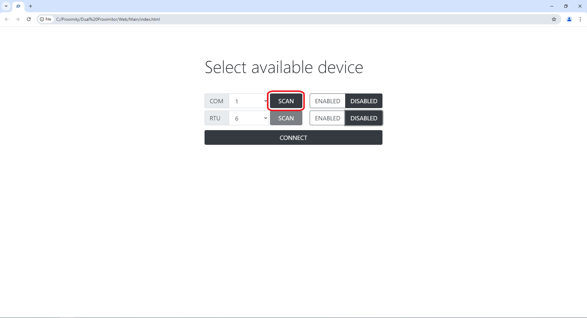
- If unsure about which COM to select, The USB Serial Port can be found in Device Manager.
If you do not see this below you may need to expand the dropdown listing the COM and LPT Ports.
- Select the appropriate COM port from the dropdown menu.

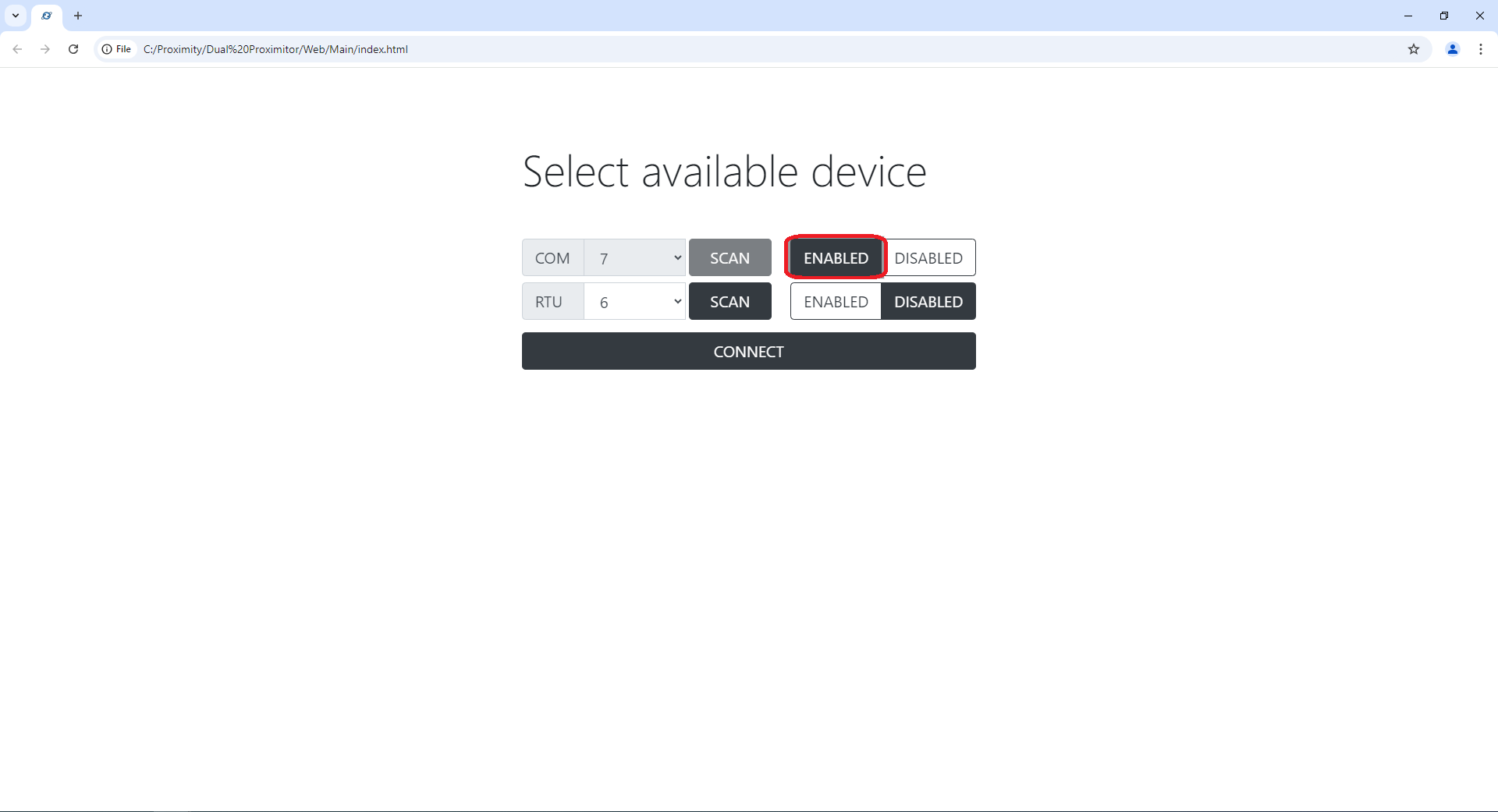
- The selected COM port should then be set to [ENABLED].

- Now that the COM port is selected and set to [ENABLED].
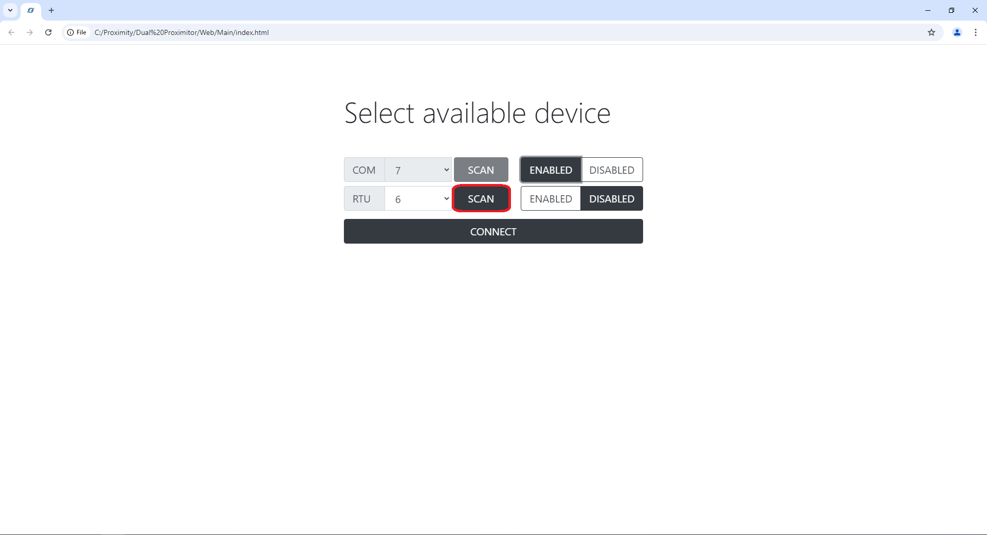
Set the RTU to [DISABLED].
Click the RTU [SCAN] button to allow the software to scan for the attached TwinProx RTU.
- After the scan is completed, select the found RTU from the populated dropdown menu.
After selecting the RTU from the dropdown, RTU should be set to [ENABLED].
Click [CONNECT] button.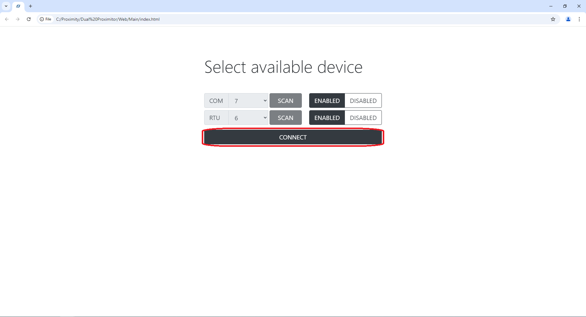


3 Main Screens of the User Interface
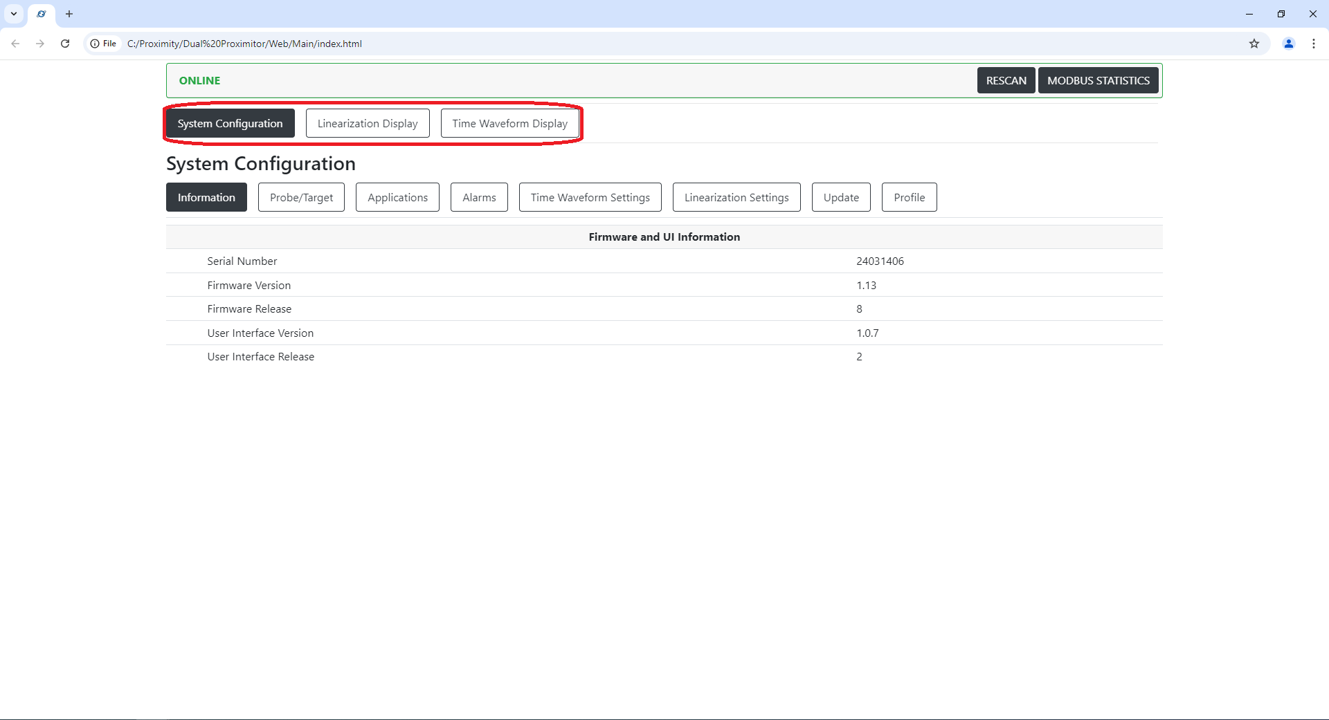
System Configuration
The system configuration screen allows the user to change various settings related to the TwinProx device and the measurements calculated by the Graphical User Interface and the PC that it is running on.
Information
Includes details about the connected TwinProx module's serial number, firmware version, and the GUI version. 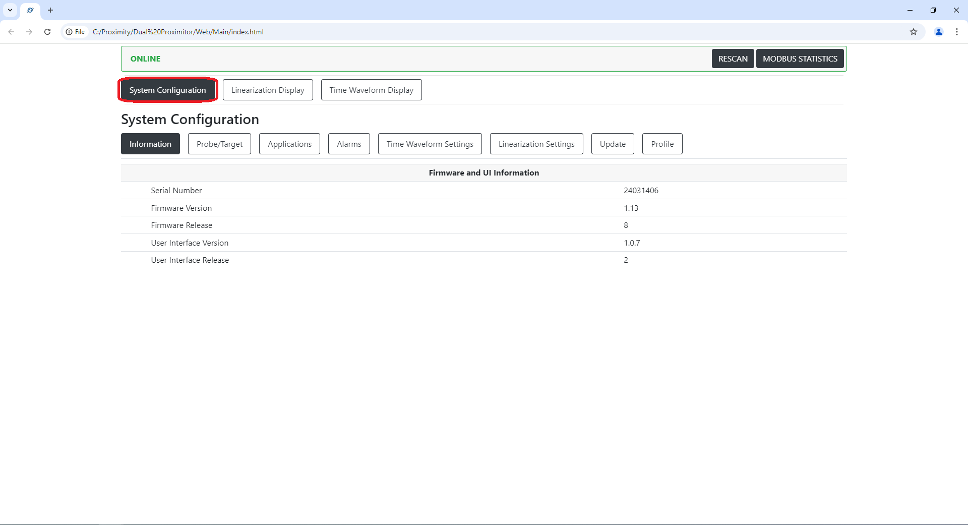
Probe / Target
Includes details about the connected TwinProx module's programmed settings for probe series, system length, and target material.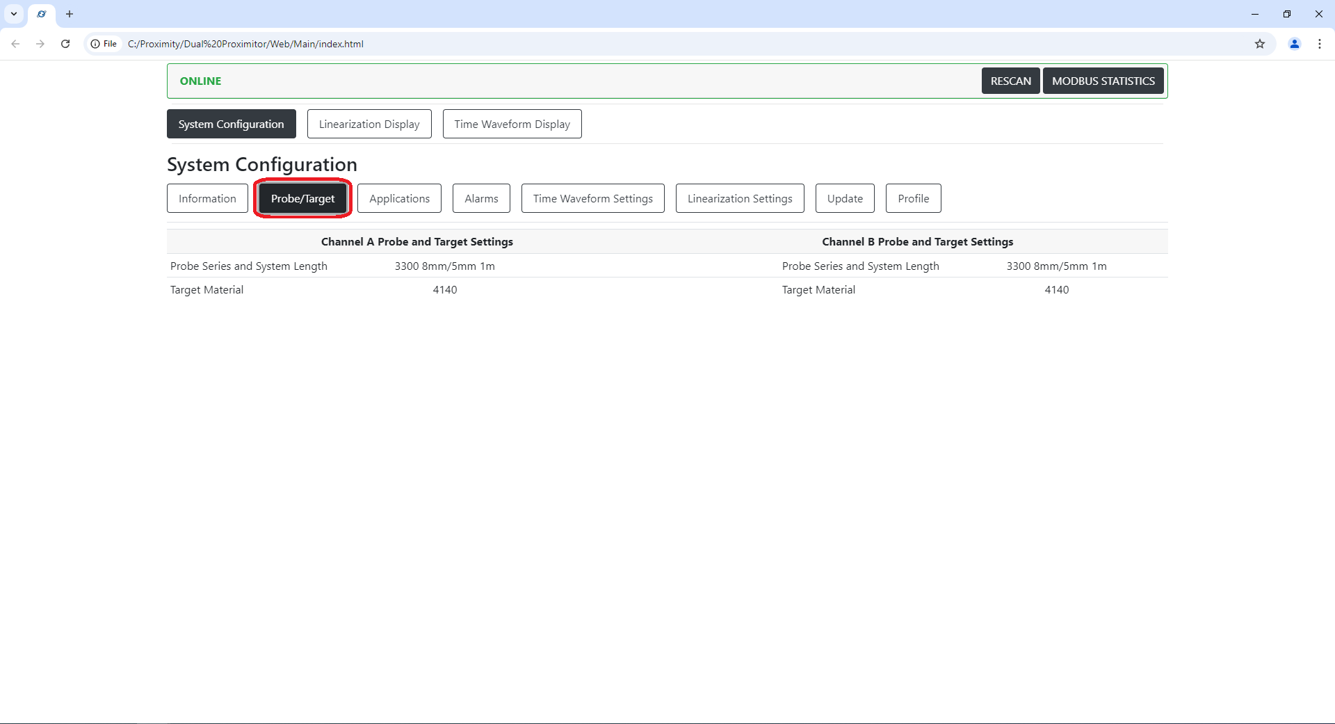
Applications
Includes details about the connected TwinProx module's programmed settings for machine speed, application selection, and notch detection thresholds (for a Phase Reference Probe).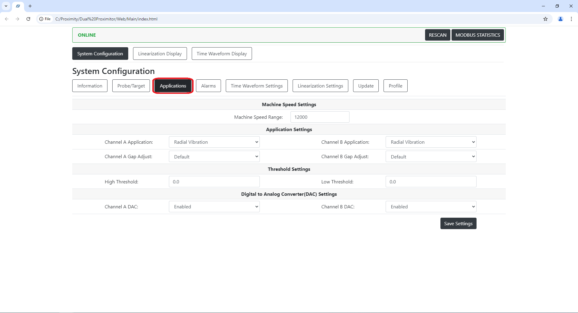
Application Settings (Advanced)
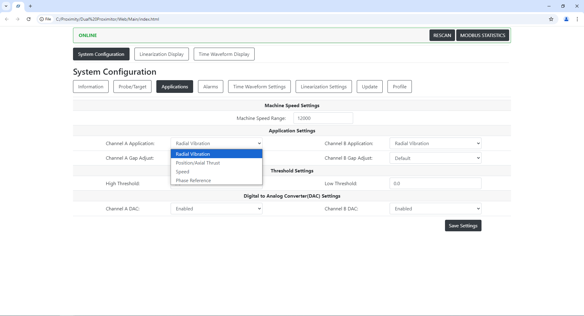
Select an Application
Radial Vibration
Position/Axial Thrust
Speed
Phase Reference
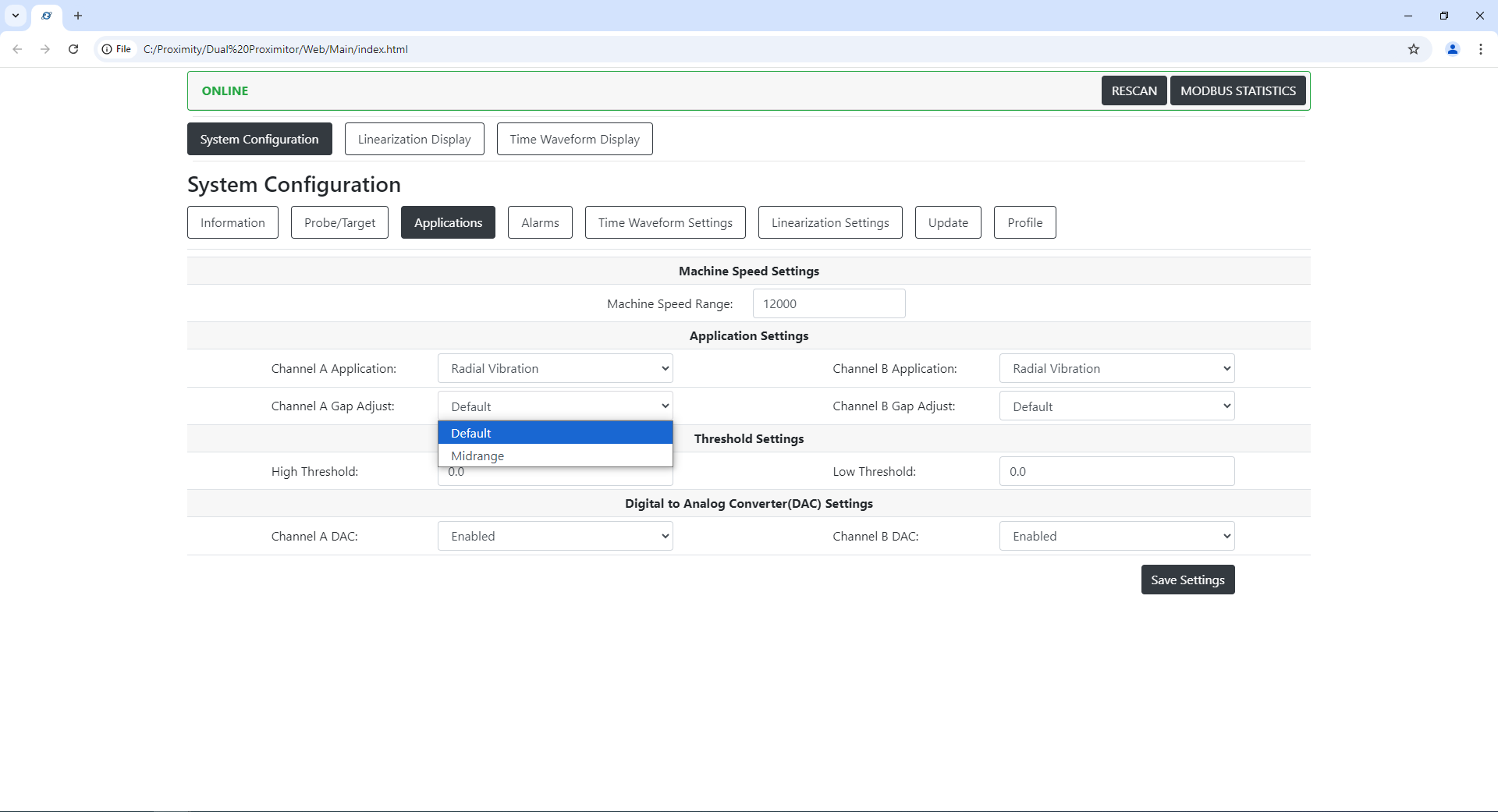
Adjust Gap LED Settings
Default vs Midrange Gap Adjust
VIB 1 (low noise) (default for vibration, speed and phase reference)
15.0-30 red
30-35 flashing red
35-45 green solid (40)
45-50 flashing blue
50-95 blue
VIB 2 (mid range)
15-40 red
40-45 flashing red
45-55 green solid (55)
55-60 flashing blue
45-95 blue
For Axial Position / Thrust (distance) the green solid LED must be more precise (X +/- 0.5 mil)
3 settings:
Position 1 (low)
15.0-25 red
25-29.5 flashing red
29.5-30.5 green solid (30 mil)
30.5-35 flashing blue
35-95 blue
Position 2 (mid) (default for position)
15.0-50 red
50-54.5 flashing red
54.5-55.5 green solid (55 mil)
55.5-60 flashing blue
60-95 blue
Position 3 (high)
15.0-75 red
75-79.5 flashing red
79.5-80.5 green solid (80 mil)
80.5-85 flashing blue
85-95 blue
Phase Reference Notch Detection High/Low Threshold
Note: The High and Low threshold can be ignored if there is no phase reference probe & notch to be measured.
First the user must install the phase reference probe and set the desired Gap setting.
Run the machine a few rotations to determine the normal distance peak as indicated in the diagram.
Also, as the machine shaft rotates, take note of the peak distance for the rising and falling edge of the phase reference notch as it passes by the face of the probe within the probe's measurement range.
The High and Low threshold is a distance setpoint.
For the High threshold, use a setpoint that is above the normal distance peak, but is under the maximum distance of the phase reference notch.
For the Low threshold, use a setpoint that is above the normal distance peak, but is under the High threshold distance setpoint.
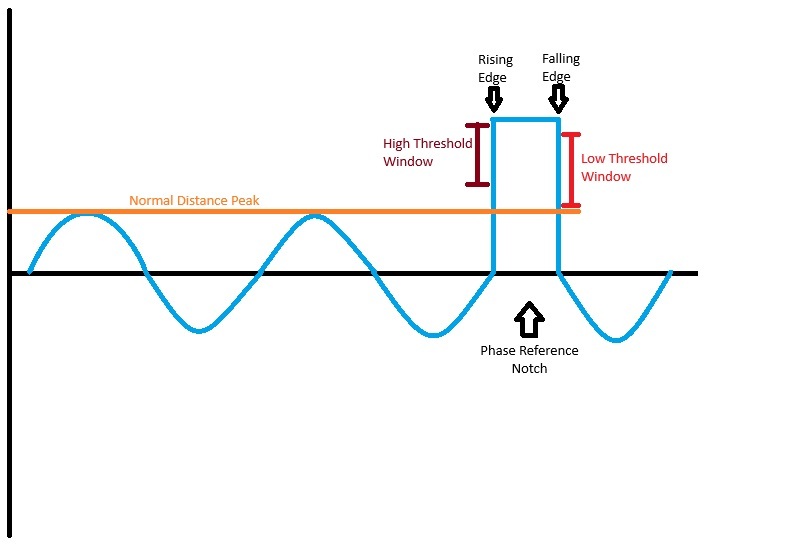
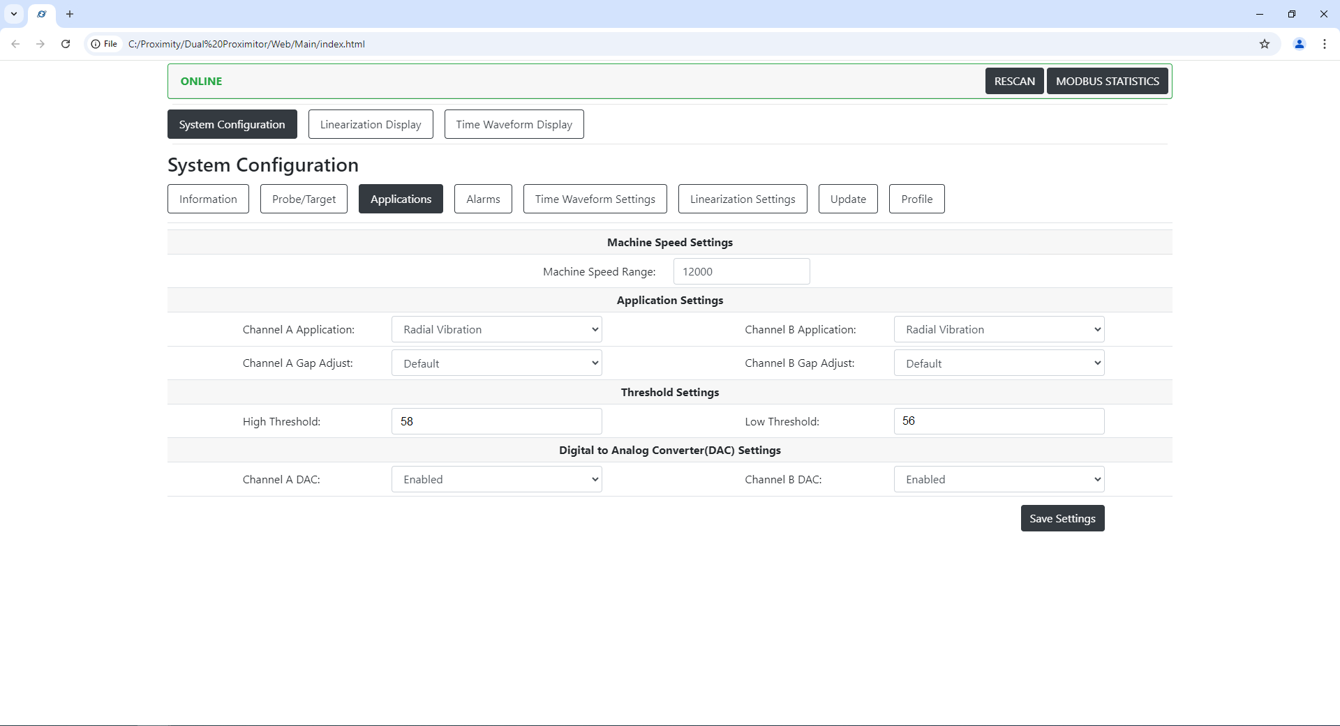
Example Above:
The Normal distance peak recorded is 50 mils.
The Peak distance for the rising and falling edge is 60 mils.
To detect the notch I would set the high threshold around 58 mils. and the low threshold around 56 mils.
That means when the TwinProx sees 58mils it knows that is the leading edge of the notch, when the distance drops past 56 mils it knows that is the end of the notch and we are on the falling edge. Therefore it will make a gap in the corresponding orbital plot for the connected Radial vibration probes to indicate where in the rotation the notch is for analysis purposes.
DAC Enabled/Disabled
For a TwinProx Voltage Out this setting should always be enabled.
If Channel A is [ENABLED] then the SIG A (Yellow) terminal and COM will produce a voltage output, in the range of 0 to -24 volts, proportional to the vibration level measured by Channel A at 200mv/mil.
If Channel B is [ENABLED] then the SIG B (Blue) terminal and COM will produce a voltage output, in the range of 0 to -24 volts, proportional to the vibration level measured by Channel B.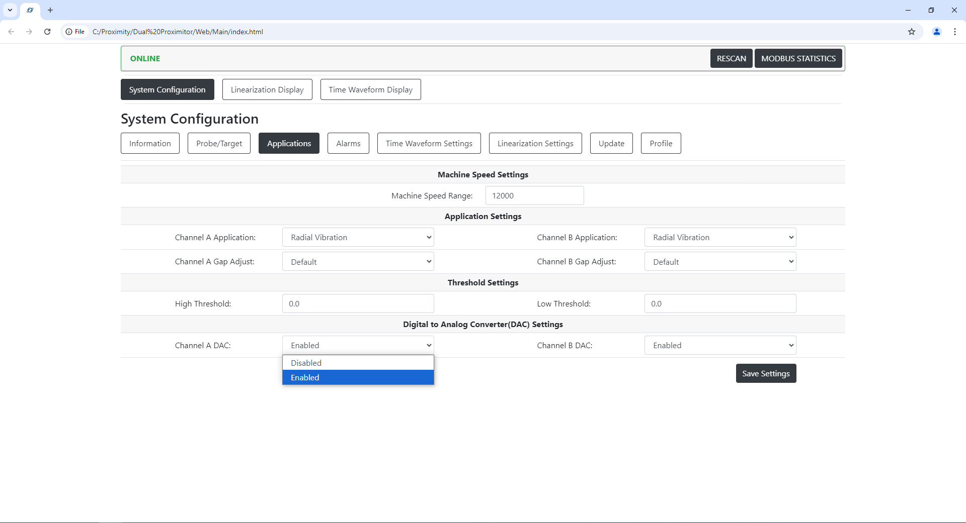
Alarms
Includes details about the connected TwinProx module's programmed alarm limits for vibration.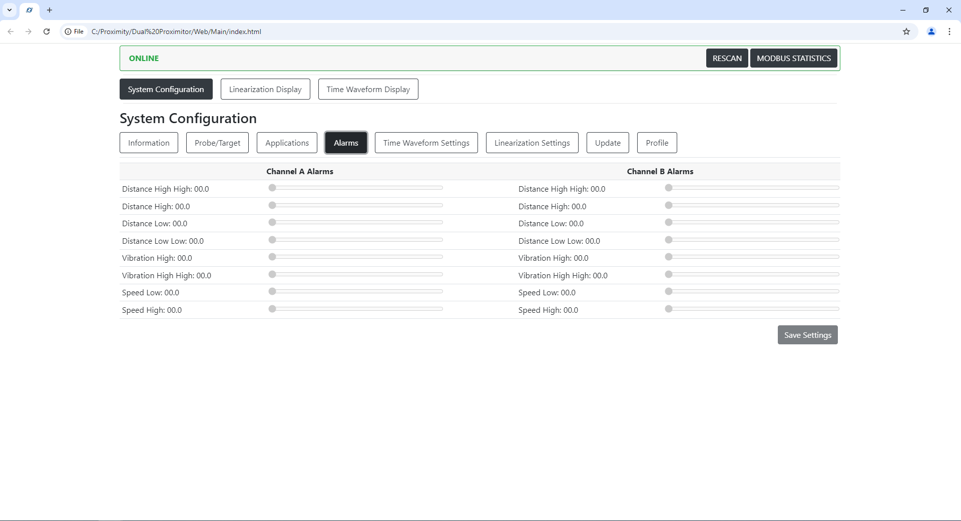
Time Waveform Settings
Includes details about the connected TwinProx module's programmed settings for changing the time waveform settings. Settings such as averaging, Total Run Out (TRO), and inverting the y-axis of the waveform.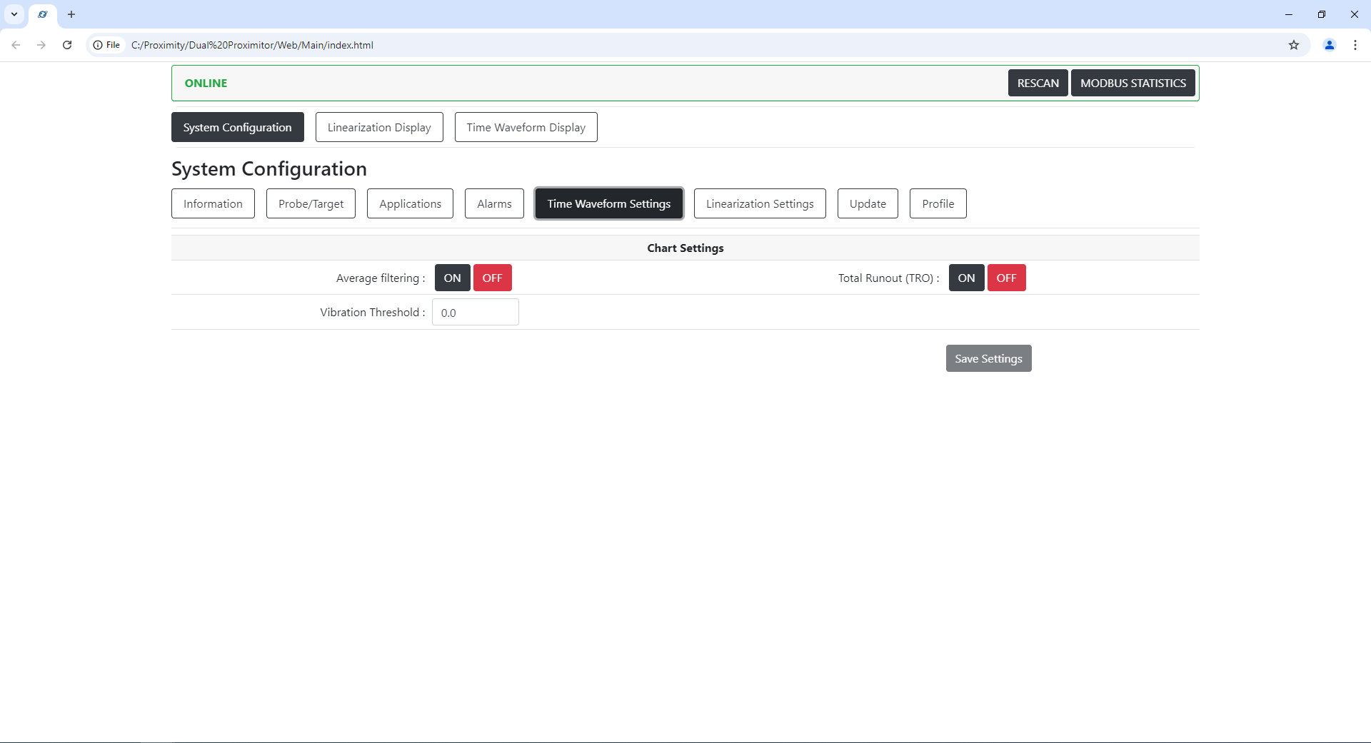
Linearization Settings
This page can be used to reset the TwinProx to factory linearization settings.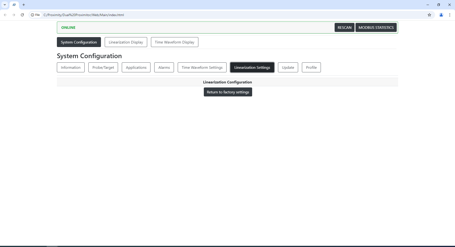
Update
If needed, the Machine Saver team may provide updates to TwinProx firmware adding and improving features as we grow. The update menu takes a Machine Saver firmware .bin file and allows the user to update the firmware from the GUI.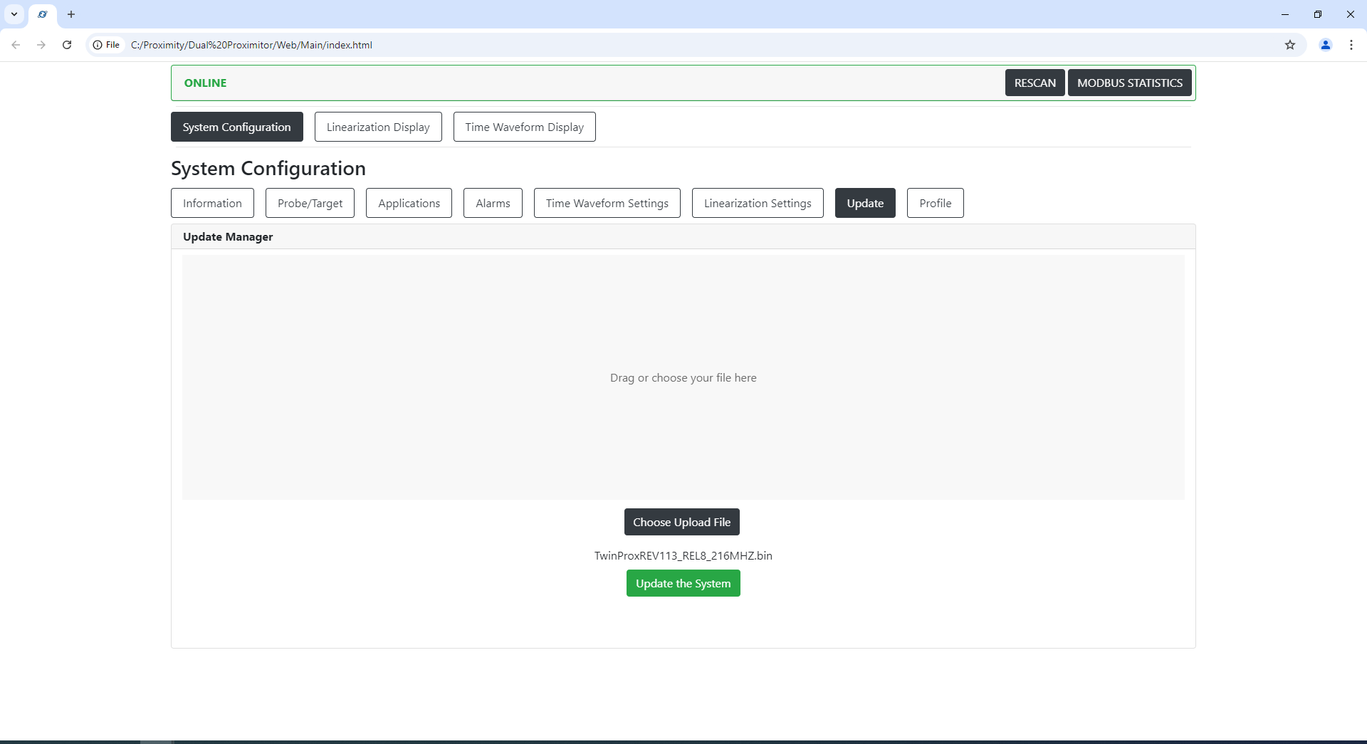
Profile
For customers who need to switch between different probes and target materials and even transfer settings to replacement devices in the field which should be linearized before use.
Select Profile from PC allows a user to select from predefined proximity probe profiles and settings for easy setup/configuration.
Download will take the current profile that is saved on the TwinProx and save it to your local PC.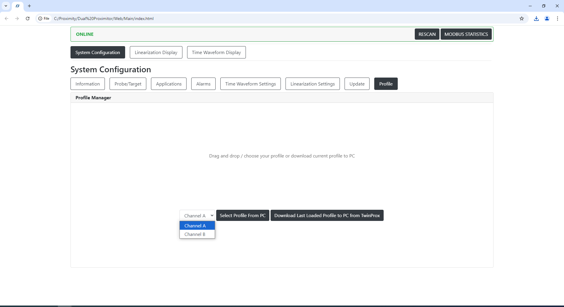
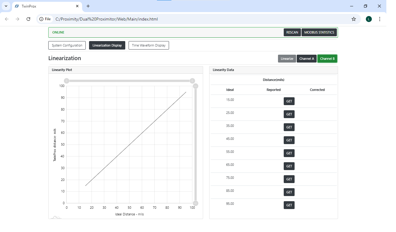
Linearization
Linearization page is to help customers setup a TwinProx for unique target and other proximity probe systems.
Procedure: ProxiTouch Linearization
- Position the Proximity Probe
Securely place the proximity probe in the static calibrator, ensuring proper
alignment for accurate calibration. - Zero the Probe
Adjust the proximity probe to make contact with the target material, ensuring
it reads zero on the display. - Lock the Probe
Once zeroed, lock the proximity probe in place to maintain consistent
positioning. - Select the Channel
Choose the channel to be linearized by clicking either Channel A or Channel
B in the top right corner of the interface.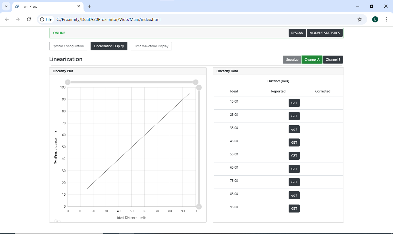

- Set Target Distance to 15 Mils
Use the static calibrator to move the target material to a distance of 15 mils
from the probe. - Capture the Reading at 15 Mils
Click the Get button next to the 15 mils setting to record the measurement. - Increase Distance and Capture Readings
Incrementally increase the distance by 10 mils, moving to 25, 35, 45, 55, 65,
75, 85, and finally 95 mils.
oAfter each increment, click the Get button to capture the reading. - Stop at 95 Mils
Stop increasing the distance once you reach 95 mils. - Linearize the Probe
Click the Linearize button to apply the linearization settings, then wait for
the Twinprox device to reboot. - Verify Calibration
Repeat steps 5-8 to verify that the linearization process was completed
successfully.

Linearization Video Instructions (Part 1)
Linearization Video Instructions (Part 2)
Automated Linearization (High Precision Probulator)
Time Waveform Display
This is the part of the User Interface that allows a customer to analyze live proximity probe data.
may be selected by the user and then the may be clicked.
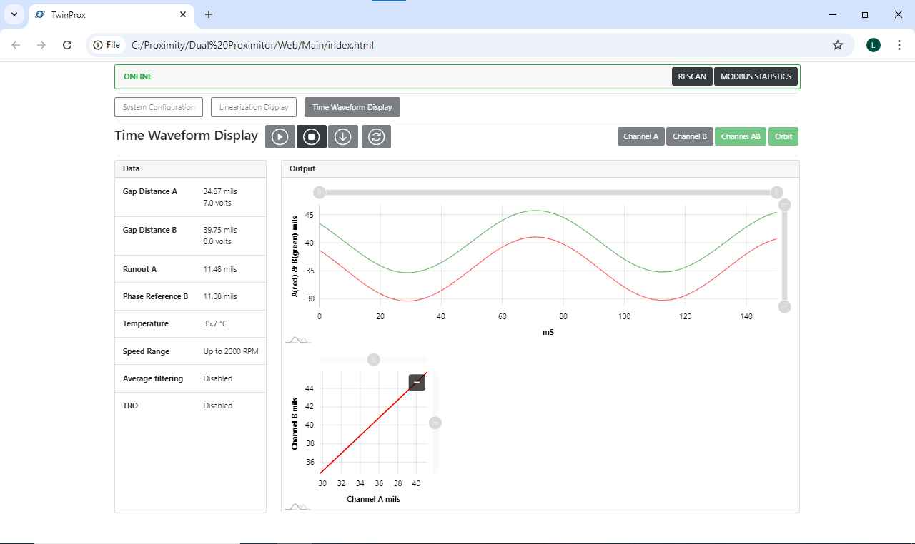
To see information from your probes:
- Select up to 3 charts from the 4 available chart view buttons on the right hand side of the screen [Channel A] [Channel B] [Channel AB] and/or [Orbit].
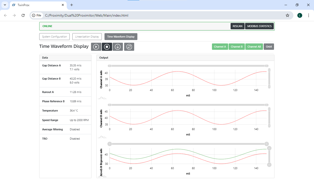

- Click the [Play Button ▶️].
Data and Output should be populated with measurements and waveforms, respectively.

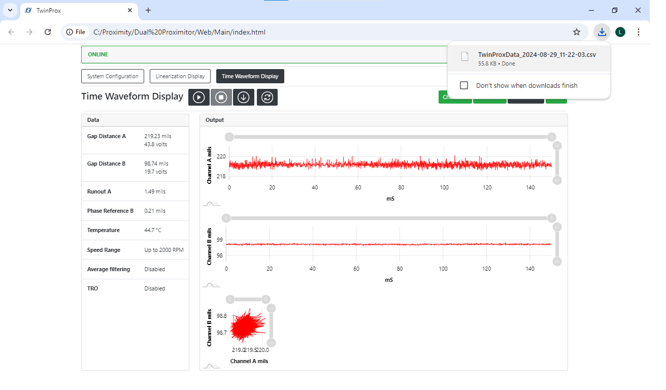
To stop information coming from the probes:
- Click the [Stop Button ⏹️].
Note: The data should be stopped before attempting to switch to another menu Or attempting to download the data and save to your PC or a flash drive.
To download the currently displayed data into a CSV:
- Click the [Download Button ⬇️].
- Make sure that the file shows as a CSV being downloaded on your PC's web browser.


Other Information
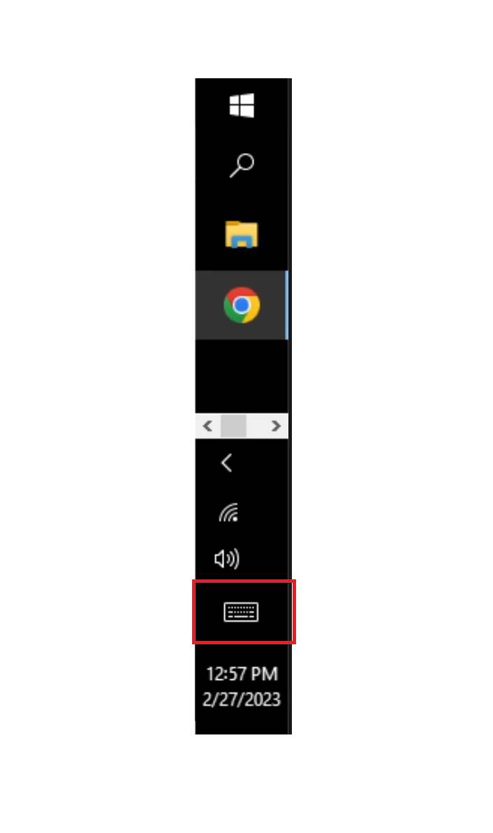
- Using the Onscreen Keyboard (Manually)
Touch on the Taskbar the Keyboard
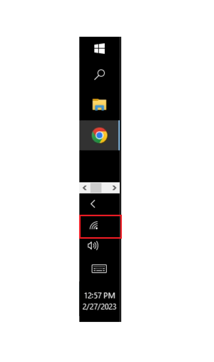
Remote Support
- If you should require remote support, click the network button on the taskbar.
- Make sure that you are connected to a network.

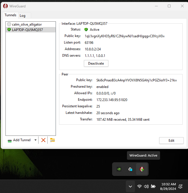
- Verify that Wireguard is running and provide information for your device's Wireguard IP address to a Machine Saver remote support technician.
Wireguard can be found in the Taskbar by looking at the picture below.
Wireguard should be [ACTIVATED].
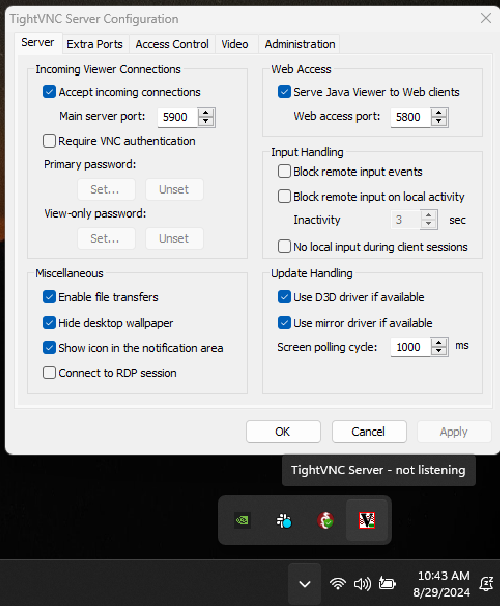
- Verify that TightVNC Server is running.
TightVNC Server can be found in the Taskbar by looking at the picture below.
TightVNC Server should be listening (note that the picture below does not show the listening state).
No Comments