3000 Specifications and Dimensions
|
Parameter |
Value |
|
Linear Range |
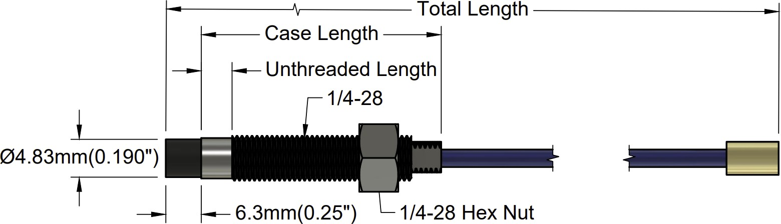
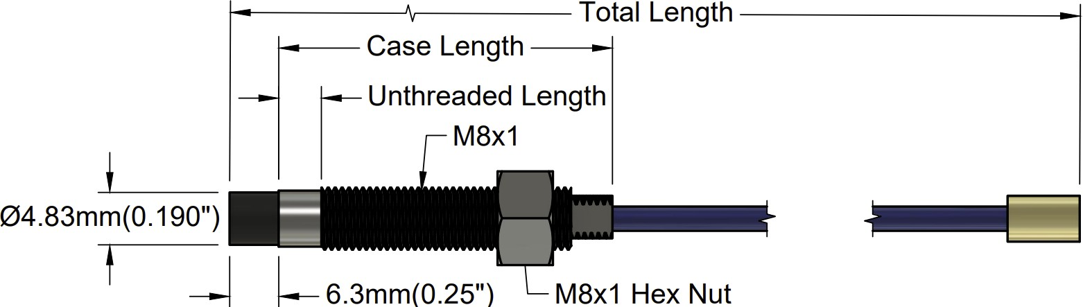
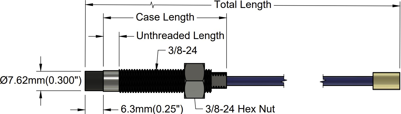
0.190” 1.43 mm (45 mils) Linear range begins at 0.25 mm (10 mils) to 1.40 mm (55 mils) 0.300” 1.53 mm (60 mils) Linear range begins at 0.25 mm (10 mils) to 1.78 mm (70 mils) |
Incremental Scale Factor (ISF)
|
7.87 V/mm (200 mV/mil) +/-10% error (including interchangeability error) when measured in 10 mil increments when measured in increments of 0.25 mm (10 mils) over the linear range. |
|
Deviation from best fit straight line (DSL) |
15 ft. system length is less than ±0.05 mm (±2 mil). 20 ft. system length is less than ±0.076 mm (±3 mil). |
|
Frequency response |
0 to 10kHz (-3 dB) typical, with up to 100 meters (300 feet) of field wiring |
|
Target Size |
Minimum flat: 25 mm (1.0 in) diameter Minimum perpendicular to shaft 50mm (2 in.) Recommended perpendicular to shaft 75mm (3 in.) |
|
Probe Tip Material |
Polyphenylene sulfide (PPS). |
|
Probe Cable Specifications |
50 Ω coaxial, fluoroethylene propylene (FEP) insulated probe cable |
|
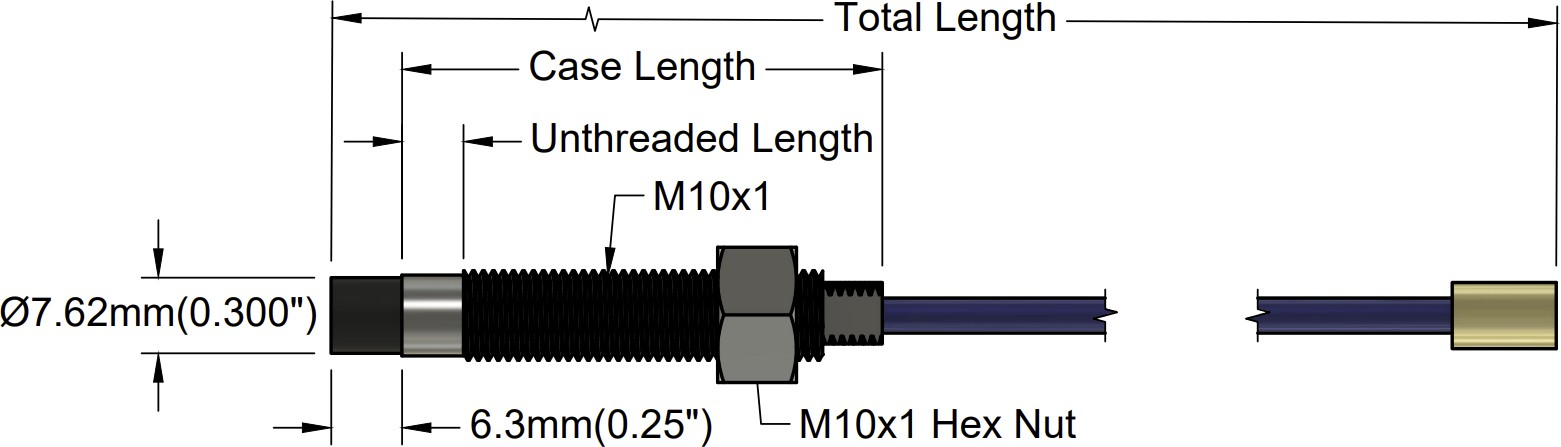
Probe Case Material |
AISI 303 or 304 stainless steel (SST). |
|
Extension Cable Material |
95 Ω coaxial, fluoroethylene propylene (FEP) insulated extension cable |
|
System Length |
15 ft or 20 ft. |
|
Extension Cable Armor (optional) |
Flexible AISI 302 SST with/without FEP outer jacket. |
|
Tensile Strength (maximum rated) |
220 N (50 lb) probe case to probe lead. 220 N (50 lb) at probe lead to extension cable connectors. 220 N (50 lb) probe case to stainless steel armor. |
|
Connector material |
Gold-plated brass |
|
Recommended Connector Torque |
Hand tightened |
|
Maximum torque |
0.56 N• m (5 in• lb) |
|
Minimum bend Radius (with or without SS armor) |
25.4 mm (1.0 in) |
Electrical
Linear Range:
0.190” 1.43 mm (45 mils) Linear range begins at 0.25 mm (10 mils) to 1.40 mm (55 mils)
0.300” 1.53 mm (60 mils) Linear range begins at 0.25 mm (10 mils) to 1.78 mm (70 mils)
Incremental Scale Factor (ISF):
7.87 V/mm (200 mV/mil) +/-10% error (including interchangeability error) when measured in 10
mil increments when measured in increments of 0.25 mm (10 mils) over the linear range.
Deviation from best fit straight line (DSL):
15 ft. system length is less than ±0.05 mm (±2 mil).
20 ft. system length is less than ±0.076 mm (±3 mil).
Frequency response:
0 to 10kHz (-3 dB) typical, with up to 100 meters (300 feet) of field wiring.
Target Size:
Minimum flat: 25 mm (1.0 in) diameter
Minimum perpendicular to shaft 50mm (2 in.)
Recommended perpendicular to shaft 75mm (3 in.)
Mechanical
Probe Tip Material:
Polyphenylene sulfide (PPS).
Probe Case Material:
AISI 303 or 304 stainless steel (SST).
Probe Cable Specifications:
50 Ω coaxial, fluoroethylene propylene (FEP) insulated probe cable.
Extension Cable Material:
95 Ω coaxial, fluoroethylene propylene (FEP) insulated extension cable.
System Length:
15 ft or 20 ft.
Extension Cable Armor (optional):
Flexible AISI 302 SST with/without FEP outer jacket.
Tensile Strength (maximum rated):
220 N (50 lb) probe case to probe lead. 220 N (50 lb) at probe lead to extension cable connectors. 220 N (50 lb) probe case to stainless steel armor.
Connector material:
Gold-plated brass.
Recommended Connector Torque:
Hand-tightened.
Maximum torque:
0.56 N• m (5 in• lb).
Minimum bend Radius (with or without SS armor):
25.4 mm (1.0 in).
Environmental Limits
Probe Temperature Range
Operating Temperature:
-34°C to +125°C (-30°F to +257°F)
Storage Temperature:
-51°C to +125°C (-60°F to +257°F)
Extension Cable Temperature Range
Operating and Storage Temperature:
-51°C to +125°C (-60°F to +257°F).
Storage Temperature:
-51°C to +125°C (-60°F to +257°F).
Proximity Sensor Temperature Range
Operating Temperature:
-35°C to +125°C (-31°F to +257°F).
Storage Temperature:
-51°C to +125°C (-60°F to +257°F).
Relative Humidity:
100% condensing, non-submersible when connectors are protected.
No Comments